
Page 212 - The Mechatronics Handbook
P. 212
0066_Frame_C11 Page 18 Wednesday, January 9, 2002 4:14 PM
FIGURE 11.27 Illustration of Thévenin theorem.
FIGURE 11.28 Illustration of Norton theorem.
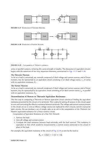
FIGURE 11.29 Computation of Thévenin resistance.
series or parallel resistors, reflecting this same principle of duality. The discussion of equivalent circuits
begins with the statement of two very important theorems, summarized in Figs. 11.27 and 11.28.
The Thévenin Theorem
As far as a load is concerned, any network composed of ideal voltage and current sources, and of linear
resistors, may be represented by an equivalent circuit consisting of an ideal voltage source, v T , in series
with an equivalent resistance, R T .
The Norton Theorem
As far as a load is concerned, any network composed of ideal voltage and current sources, and of linear
resistors, may be represented by an equivalent circuit consisting of an ideal current source, i N , in parallel
with an equivalent resistance, R N .
Determination of Norton or Thévenin Equivalent Resistance
The first step in computing a Thévenin or Norton equivalent circuit consists of finding the equivalent
resistance presented by the circuit at its terminals. This is done by setting all sources in the circuit equal
to zero and computing the effective resistance between terminals. The voltage and current sources present
in the circuit are set to zero as follows: voltage sources are replaced by short circuits, current sources by
open circuits. We can produce a set of simple rules as an aid in the computation of the Thévenin (or
Norton) equivalent resistance for a linear resistive circuit.
Computation of Equivalent Resistance of a One-Port Network:
1. Remove the load.
2. Zero all voltage and current sources
3. Compute the total resistance between load terminals, with the load removed. This resistance is
equivalent to that which would be encountered by a current source connected to the circuit in
place of the load.
For example, the equivalent resistance of the circuit of Fig. 11.29 as seen by the load is:
R = ((2||2) + 1)||2 = 1 Ω.
eq
©2002 CRC Press LLC