
Page 216 - The Mechatronics Handbook
P. 216
0066_Frame_C11 Page 22 Wednesday, January 9, 2002 4:14 PM
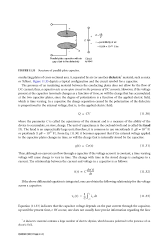
FIGURE 11.35 Structure of parallel-plate capacitor.
∗
conducting plates of cross-sectional area A, separated by air (or another dielectric material, such as mica
or Teflon). Figure 11.35 depicts a typical configuration and the circuit symbol for a capacitor.
The presence of an insulating material between the conducting plates does not allow for the flow of
DC current; thus, a capacitor acts as an open circuit in the presence of DC currents. However, if the voltage
present at the capacitor terminals changes as a function of time, so will the charge that has accumulated
at the two capacitor plates, since the degree of polarization is a function of the applied electric field,
which is time-varying. In a capacitor, the charge separation caused by the polarization of the dielectric
is proportional to the external voltage, that is, to the applied electric field:
Q = CV (11.30)
where the parameter C is called the capacitance of the element and is a measure of the ability of the
device to accumulate, or store, charge. The unit of capacitance is the coulomb/volt and is called the farad
−6
(F). The farad is an unpractically large unit; therefore, it is common to use microfarads (1 µF = 10 F)
–12
or picofarads (1 pF = 10 F). From Eq. (11.30) it becomes apparent that if the external voltage applied
to the capacitor plates changes in time, so will the charge that is internally stored by the capacitor:
qt() = Cv t() (11.31)
Thus, although no current can flow through a capacitor if the voltage across it is constant, a time-varying
voltage will cause charge to vary in time. The change with time in the stored charge is analogous to a
current. The relationship between the current and voltage in a capacitor is as follows:
dv t()
it() = C ------------ (11.32)
dt
If the above differential equation is integrated, one can obtain the following relationship for the voltage
across a capacitor:
1
v C t() = --- ∫ t 0 i C dt (11.33)
C – ∞
Equation (11.33) indicates that the capacitor voltage depends on the past current through the capacitor,
up until the present time, t. Of course, one does not usually have precise information regarding the flow
∗
A dielectric material contains a large number of electric dipoles, which become polarized in the presence of an
electric field.
©2002 CRC Press LLC