
Page 218 - The Mechatronics Handbook
P. 218
0066_Frame_C11 Page 24 Wednesday, January 9, 2002 4:14 PM
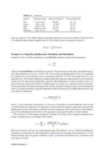
TABLE 11.3 Capacitors
Material Capacitance Range Maximum Voltage (V) Frequency Range (Hz)
3
Mica 1 pF to 0.1 µF 100–600 10 –10 10
3
Ceramic 10 pF to 1 µF 50–1000 10 –10 10
2
Mylar 0.001 to 10 µF 50–500 10 –10 8
2
Paper 1000 pF to 50 µF 100–105 10 –10 8
Electrolytic 0.1 µF to 0.2 F 3–600 10–10 4
types of capacitors. The voltage rating is particularly important, because any insulator will break down
if a sufficiently high voltage is applied across it. The energy stored in a capacitor is given by
--Cv C t() J()
W C t() = 1 2
2
Example 11.3 Capacitive Displacement Transducer and Microphone
As shown in Fig. 11.26, the capacitance of a parallel-plate capacitor is given by the expression
C = eA
------
d
where ε is the permittivity of the dielectric material, A the area of each of the plates, and d their separa-
2
–12
tion. The permittivity of air is ε 0 = 8.854 × 10 F/m, so that two parallel plates of area 1 m , separated
–3
by a distance of 1 mm, would give rise to a capacitance of 8.854 × 10 µF, a very small value for a very
large plate area. This relative inefficiency makes parallel-plate capacitors impractical for use in electronic
circuits. On the other hand, parallel-plate capacitors find application as motion transducers, that is, as
devices that can measure the motion or displacement of an object. In a capacitive motion transducer,
the air gap between the plates is designed to be variable, typically by fixing one plate and connecting the
other to an object in motion. Using the capacitance value just derived for a parallel-plate capacitor, one
can obtain the expression
–
3
C = 8.854 × 10 A
----------------------------------
x
where C is the capacitance in picofarad, A is the area of the plates in square millimeter, and x is the
(variable) distance in milimeter. It is important to observe that the change in capacitance caused by the
displacement of one of the plates is nonlinear, since the capacitance varies as the inverse of the displace-
ment. For small displacements, however, the capacitance varies approximately in a linear fashion.
The sensitivity, S, of this motion transducer is defined as the slope of the change in capacitance per
change in displacement, x, according to the relation
3
–
------- =
S = dC – 8.854 × 10 A )
---------------------------------- pF/mm(
dx 2x 2
Thus, the sensitivity increases for small displacements. This behavior can be verified by plotting the
capacitance as a function of x and noting that as x approaches zero, the slope of the nonlinear C(x) curve
becomes steeper (thus the greater sensitivity). Figure 11.38 depicts this behavior for a transducer with
2
area equal to 10 mm .
©2002 CRC Press LLC