
Page 217 - The Mechatronics Handbook
P. 217
0066_Frame_C11 Page 23 Wednesday, January 9, 2002 4:14 PM
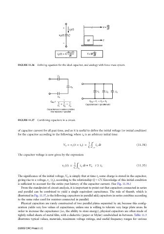
FIGURE 11.36 Defining equation for the ideal capacitor, and analogy with force-mass system.
FIGURE 11.37 Combining capacitors in a circuit.
of capacitor current for all past time, and so it is useful to define the initial voltage (or initial condition)
for the capacitor according to the following, where t 0 is an arbitrary initial time:
1
(
V 0 = v C t = t 0 ) = --- ∫ t i C dt (11.34)
C – ∞
The capacitor voltage is now given by the expression
v C t() = 1 ∫ t i C t + V 0 t ≥ t 0 (11.35)
---
d
C t 0
The significance of the initial voltage, V 0 , is simply that at time t 0 some charge is stored in the capacitor,
giving rise to a voltage, v C (t 0 ), according to the relationship Q = CV. Knowledge of this initial condition
is sufficient to account for the entire past history of the capacitor current. (See Fig. 11.36.)
From the standpoint of circuit analysis, it is important to point out that capacitors connected in series
and parallel can be combined to yield a single equivalent capacitance. The rule of thumb, which is
illustrated in Fig. 11.37, is the following: capacitors in parallel add; capacitors in series combine according
to the same rules used for resistors connected in parallel.
Physical capacitors are rarely constructed of two parallel plates separated by air, because this config-
uration yields very low values of capacitance, unless one is willing to tolerate very large plate areas. In
order to increase the capacitance (i.e., the ability to store energy), physical capacitors are often made of
tightly rolled sheets of metal film, with a dielectric (paper or Mylar) sandwiched in-between. Table 11.3
illustrates typical values, materials, maximum voltage ratings, and useful frequency ranges for various
©2002 CRC Press LLC