
Page 219 - The Mechatronics Handbook
P. 219
0066_Frame_C11 Page 25 Wednesday, January 9, 2002 4:14 PM
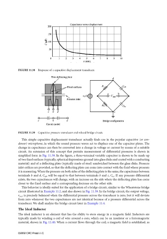
FIGURE 11.38 Response of a capacitive displacement transducer.
FIGURE 11.39 Capacitive pressure transducer and related bridge circuit.
This simple capacitive displacement transducer actually finds use in the popular capacitive (or con-
denser) microphone, in which the sound pressure waves act to displace one of the capacitor plates. The
change in capacitance can then be converted into a change in voltage or current by means of a suitable
circuit. An extension of this concept that permits measurement of differential pressures is shown in
simplified form in Fig. 11.39. In the figure, a three-terminal variable capacitor is shown to be made up
of two fixed surfaces (typically, spherical depressions ground into glass disks and coated with a conducting
material) and of a deflecting plate (typically made of steel) sandwiched between the glass disks. Pressure
inlet orifices are provided, so that the deflecting plate can come into contact with the fluid whose pressure
it is measuring. When the pressure on both sides of the deflecting plate is the same, the capacitance between
terminals b and d, C bd , will be equal to that between terminals b and c, C bc . If any pressure differential
exists, the two capacitances will change, with an increase on the side where the deflecting plate has come
closer to the fixed surface and a corresponding decrease on the other side.
This behavior is ideally suited for the application of a bridge circuit, similar to the Wheatstone bridge
circuit illustrated in Example 11.2, and also shown in Fig. 11.39. In the bridge circuit, the output voltage,
v out , is precisely balanced when the differential pressure across the transducer is zero, but it will deviate
from zero whenever the two capacitances are not identical because of a pressure differential across the
transducer. We shall analyze the bridge circuit later in Example 11.4.
The Ideal Inductor
The ideal inductor is an element that has the ability to store energy in a magnetic field. Inductors are
typically made by winding a coil of wire around a core, which can be an insulator or a ferromagnetic
material, shown in Fig. 11.40. When a current flows through the coil, a magnetic field is established, as
©2002 CRC Press LLC