
Page 220 - The Mechatronics Handbook
P. 220
0066_Frame_C11 Page 26 Wednesday, January 9, 2002 4:14 PM
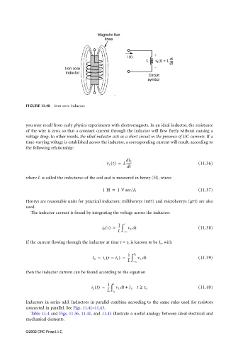
FIGURE 11.40 Iron-core inductor.
you may recall from early physics experiments with electromagnets. In an ideal inductor, the resistance
of the wire is zero, so that a constant current through the inductor will flow freely without causing a
voltage drop. In other words, the ideal inductor acts as a short circuit in the presence of DC currents. If a
time-varying voltage is established across the inductor, a corresponding current will result, according to
the following relationship:
di L
v L t() = L------- (11.36)
dt
where L is called the inductance of the coil and is measured in henry (H), where
1 H = 1 V sec/A (11.37)
Henrys are reasonable units for practical inductors; millihenrys (mH) and microhenrys (µH) are also
used.
The inductor current is found by integrating the voltage across the inductor:
i L t() = 1 ∫ t v L dt (11.38)
---
L – ∞
If the current flowing through the inductor at time t = t 0 is known to be I 0 , with
1
(
I 0 = i L t = t 0 ) = --- ∫ t 0 v L dt (11.39)
L – ∞
then the inductor current can be found according to the equation
i L t() = 1 ∫ t v L t + I 0 t ≥ t 0 (11.40)
d
---
L t 0
Inductors in series add. Inductors in parallel combine according to the same rules used for resistors
connected in parallel. See Figs. 11.41–11.43.
Table 11.4 and Figs. 11.36, 11.41, and 11.43 illustrate a useful analogy between ideal electrical and
mechanical elements.
©2002 CRC Press LLC