
Page 215 - The Mechatronics Handbook
P. 215
0066_Frame_C11 Page 21 Wednesday, January 9, 2002 4:14 PM
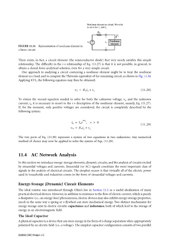
FIGURE 11.34 Representation of nonlinear element in
a linear circuit.
There exists, in fact, a circuit element (the semiconductor diode) that very nearly satisfies this simple
relationship. The difficulty in the i-v relationship of Eq. (11.27) is that it is not possible, in general, to
obtain a closed-form analytical solution, even for a very simple circuit.
One approach to analyzing a circuit containing a nonlinear element might be to treat the nonlinear
element as a load, and to compute the Thévenin equivalent of the remaining circuit, as shown in Fig. 11.34.
Applying KVL, the following equation may then be obtained:
v T = R T i x + v x (11.28)
To obtain the second equation needed to solve for both the unknown voltage, v x , and the unknown
current, i x , it is necessary to resort to the i-v description of the nonlinear element, namely, Eq. (11.27).
If, for the moment, only positive voltages are considered, the circuit is completely described by the
following system:
i x = I 0 e an x , v > 0
(11.29)
v T = R T i x + v x
The two parts of Eq. (11.29) represent a system of two equations in two unknowns. Any numerical
method of choice may now be applied to solve the system of Eqs. (11.29).
11.4 AC Network Analysis
In this section we introduce energy-storage elements, dynamic circuits, and the analysis of circuits excited
by sinusoidal voltages and currents. Sinusoidal (or AC) signals constitute the most important class of
signals in the analysis of electrical circuits. The simplest reason is that virtually all of the electric power
used in households and industries comes in the form of sinusoidal voltages and currents.
Energy-Storage (Dynamic) Circuit Elements
The ideal resistor was introduced through Ohm’s law in Section 11.2 as a useful idealization of many
practical electrical devices. However, in addition to resistance to the flow of electric current, which is purely
a dissipative (i.e., an energy-loss) phenomenon, electric devices may also exhibit energy-storage properties,
much in the same way a spring or a flywheel can store mechanical energy. Two distinct mechanisms for
energy storage exist in electric circuits: capacitance and inductance, both of which lead to the storage of
energy in an electromagnetic field.
The Ideal Capacitor
A physical capacitor is a device that can store energy in the form of a charge separation when appropriately
polarized by an electric field (i.e., a voltage). The simplest capacitor configuration consists of two parallel
©2002 CRC Press LLC