
Page 213 - The Mechatronics Handbook
P. 213
0066_Frame_C11 Page 19 Wednesday, January 9, 2002 4:14 PM
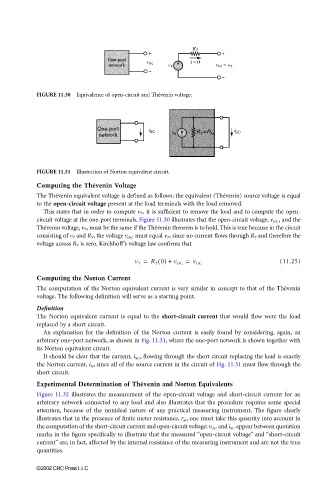
FIGURE 11.30 Equivalence of open-circuit and Thévenin voltage.
FIGURE 11.31 Illustration of Norton equivalent circuit.
Computing the Thévenin Voltage
The Thévenin equivalent voltage is defined as follows: the equivalent (Thévenin) source voltage is equal
to the open-circuit voltage present at the load terminals with the load removed.
This states that in order to compute v T , it is sufficient to remove the load and to compute the open-
circuit voltage at the one-port terminals. Figure 11.30 illustrates that the open-circuit voltage, v OC , and the
Thévenin voltage, v T , must be the same if the Thévenin theorem is to hold. This is true because in the circuit
consisting of v T and R T , the voltage v OC must equal v T , since no current flows through R T and therefore the
voltage across R T is zero. Kirchhoff’s voltage law confirms that
v T = R T 0() + v OC = v OC (11.25)
Computing the Norton Current
The computation of the Norton equivalent current is very similar in concept to that of the Thévenin
voltage. The following definition will serve as a starting point.
Definition
The Norton equivalent current is equal to the short-circuit current that would flow were the load
replaced by a short circuit.
An explanation for the definition of the Norton current is easily found by considering, again, an
arbitrary one-port network, as shown in Fig. 11.31, where the one-port network is shown together with
its Norton equivalent circuit.
It should be clear that the current, i SC , flowing through the short circuit replacing the load is exactly
the Norton current, i N , since all of the source current in the circuit of Fig. 11.31 must flow through the
short circuit.
Experimental Determination of Thévenin and Norton Equivalents
Figure 11.32 illustrates the measurement of the open-circuit voltage and short-circuit current for an
arbitrary network connected to any load and also illustrates that the procedure requires some special
attention, because of the nonideal nature of any practical measuring instrument. The figure clearly
illustrates that in the presence of finite meter resistance, r m , one must take this quantity into account in
the computation of the short-circuit current and open-circuit voltage; v OC and i SC appear between quotation
marks in the figure specifically to illustrate that the measured “open-circuit voltage” and “short-circuit
current” are, in fact, affected by the internal resistance of the measuring instrument and are not the true
quantities.
©2002 CRC Press LLC