
Page 208 - The Mechatronics Handbook
P. 208
0066_Frame_C11 Page 14 Wednesday, January 9, 2002 4:14 PM
Measuring Devices
The Ammeter
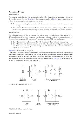
The ammeter is a device that, when connected in series with a circuit element, can measure the current
flowing through the element. Figure 11.18 illustrates this idea. From Fig. 11.18, two requirements are
evident for obtaining a correct measurement of current:
1. The ammeter must be placed in series with the element whose current is to be measured (e.g.,
resistor R 2 ).
2. The ammeter should not resist the flow of current (i.e., cause a voltage drop), or else it will not
be measuring the true current flowing the circuit. An ideal ammeter has zero internal resistance.
The Voltmeter
The voltmeter is a device that can measure the voltage across a circuit element. Since voltage is the
difference in potential between two points in a circuit, the voltmeter needs to be connected across the
element whose voltage we wish to measure. A voltmeter must also fulfill two requirements:
1. The voltmeter must be placed in parallel with the element whose voltage it is measuring.
2. The voltmeter should draw no current away from the element whose voltage it is measuring, or
else it will not be measuring the true voltage across that element. Thus, an ideal voltmeter has
infinite internal resistance.
Figure 11.19 illustrates these two points.
Once again, the definitions just stated for the ideal voltmeter and ammeter need to be augmented by
considering the practical limitations of the devices. A practical ammeter will contribute some series
resistance to the circuit in which it is measuring current; a practical voltmeter will not act as an ideal
open circuit but will always draw some current from the measured circuit. Figure 11.20 depicts the circuit
models for the practical ammeter and voltmeter.
FIGURE 11.18 Measurement of current.
FIGURE 11.19 Measurement of voltage.
©2002 CRC Press LLC