
Page 211 - The Mechatronics Handbook
P. 211
0066_Frame_C11 Page 17 Wednesday, January 9, 2002 4:14 PM
FIGURE 11.24 Basic principle of mesh analysis.
FIGURE 11.25 Use of KVL in mesh analysis.
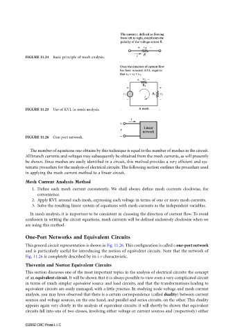
FIGURE 11.26 One-port network.
The number of equations one obtains by this technique is equal to the number of meshes in the circuit.
All branch currents and voltages may subsequently be obtained from the mesh currents, as will presently
be shown. Since meshes are easily identified in a circuit, this method provides a very efficient and sys-
tematic procedure for the analysis of electrical circuits. The following section outlines the procedure used
in applying the mesh current method to a linear circuit.
Mesh Current Analysis Method
1. Define each mesh current consistently. We shall always define mesh currents clockwise, for
convenience.
2. Apply KVL around each mesh, expressing each voltage in terms of one or more mesh currents.
3. Solve the resulting linear system of equations with mesh currents as the independent variables.
In mesh analysis, it is important to be consistent in choosing the direction of current flow. To avoid
confusion in writing the circuit equations, mesh currents will be defined exclusively clockwise when we
are using this method.
One-Port Networks and Equivalent Circuits
This general circuit representation is shown in Fig. 11.26. This configuration is called a one-port network
and is particularly useful for introducing the notion of equivalent circuits. Note that the network of
Fig. 11.26 is completely described by its i-v characteristic.
Thévenin and Norton Equivalent Circuits
This section discusses one of the most important topics in the analysis of electrical circuits: the concept
of an equivalent circuit. It will be shown that it is always possible to view even a very complicated circuit
in terms of much simpler equivalent source and load circuits, and that the transformations leading to
equivalent circuits are easily managed, with a little practice. In studying node voltage and mesh current
analysis, you may have observed that there is a certain correspondence (called duality) between current
sources and voltage sources, on the one hand, and parallel and series circuits, on the other. This duality
appears again very clearly in the analysis of equivalent circuits: it will shortly be shown that equivalent
circuits fall into one of two classes, involving either voltage or current sources and (respectively) either
©2002 CRC Press LLC