
Page 225 - The Mechatronics Handbook
P. 225
0066_Frame_C11 Page 31 Wednesday, January 9, 2002 4:14 PM
to obtain the following differential equation:
1
------- + -------i C = ---------- (11.51)
1 dv S
di C
dt RC R dt
where the argument (t) has been dropped for ease of notation.
Observe that in Eq. (11.51), the independent variable is the series current flowing in the circuit, and
that this is not the only equation that describes the series RC circuit. If, instead of applying KVL, for
example, we had applied KCL at the node connecting the resistor to the capacitor, we would have obtained
the following relationship:
i R = v S – v C i C = C -------- (11.52)
--------------- =
dv C
R dt
or
-------- + -------v C = -------v S (11.53)
dv C 1 1
dt RC RC
Note the similarity between Eqs. (11.51) and (11.53). The left-hand side of both equations is identical,
except for the dependent variable, while the right-hand side takes a slightly different form. The solution
of either equation is sufficient, however, to determine all voltages and currents in the circuit.
We can generalize the results above by observing that any circuit containing a single energy-storage
element can be described by a differential equation of the form
dy t()
a 1 ------------ + a 0 t() = Ft() (11.54)
dt
where y(t) represents the capacitor voltage in the circuit of Fig. 11.48 and where the constants a 0 and a 1
consist of combinations of circuit element parameters. Equation (11.54) is a first-order ordinary differ-
ential equation with constant coefficients.
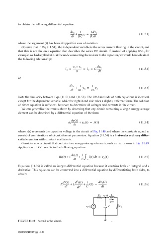
Consider now a circuit that contains two energy-storage elements, such as that shown in Fig. 11.49.
Application of KVL results in the following equation:
di t() 1 t
Ri t() + L----------- + --- ∫ it() dt = v S t() (11.55)
dt C – ∞
Equation (11.55) is called an integro-differential equation because it contains both an integral and a
derivative. This equation can be converted into a differential equation by differentiating both sides, to
obtain:
di t() d it() 1 dv S t()
2
R----------- + L------------- + ---it() = -------------- (11.56)
dt dt 2 C dt
FIGURE 11.49 Second-order circuit.
©2002 CRC Press LLC