
Page 228 - The Mechatronics Handbook
P. 228
0066_Frame_C11 Page 34 Wednesday, January 9, 2002 4:14 PM
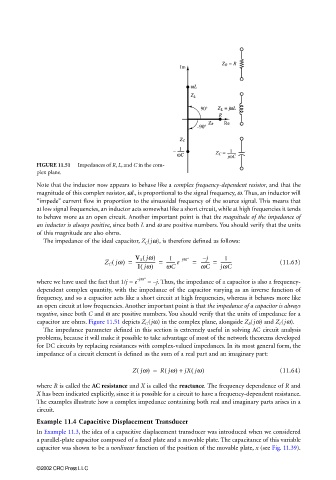
FIGURE 11.51 Impedances of R, L, and C in the com-
plex plane.
Note that the inductor now appears to behave like a complex frequency-dependent resistor, and that the
magnitude of this complex resistor, ωL, is proportional to the signal frequency, ω. Thus, an inductor will
“impede” current flow in proportion to the sinusoidal frequency of the source signal. This means that
at low signal frequencies, an inductor acts somewhat like a short circuit, while at high frequencies it tends
to behave more as an open circuit. Another important point is that the magnitude of the impedance of
an inductor is always positive, since both L and ω are positive numbers. You should verify that the units
of this magnitude are also ohms.
The impedance of the ideal capacitor, Z C (jω), is therefore defined as follows:
(
V S jw) 1 j – 1
(
Z C jw) = ------------------ = -------- e j – 90° = -------- = ---------- (11.63)
(
I jw) wC wC jwC
–j90°
where we have used the fact that 1/j = e = –j. Thus, the impedance of a capacitor is also a frequency-
dependent complex quantity, with the impedance of the capacitor varying as an inverse function of
frequency, and so a capacitor acts like a short circuit at high frequencies, whereas it behaves more like
an open circuit at low frequencies. Another important point is that the impedance of a capacitor is always
negative, since both C and ω are positive numbers. You should verify that the units of impedance for a
capacitor are ohms. Figure 11.51 depicts Z C (jω) in the complex plane, alongside Z R (jω) and Z L (jω).
The impedance parameter defined in this section is extremely useful in solving AC circuit analysis
problems, because it will make it possible to take advantage of most of the network theorems developed
for DC circuits by replacing resistances with complex-valued impedances. In its most general form, the
impedance of a circuit element is defined as the sum of a real part and an imaginary part:
Zjw) = Rjw) + jX jw) (11.64)
(
(
(
where R is called the AC resistance and X is called the reactance. The frequency dependence of R and
X has been indicated explicitly, since it is possible for a circuit to have a frequency-dependent resistance.
The examples illustrate how a complex impedance containing both real and imaginary parts arises in a
circuit.
Example 11.4 Capacitive Displacement Transducer
In Example 11.3, the idea of a capacitive displacement transducer was introduced when we considered
a parallel-plate capacitor composed of a fixed plate and a movable plate. The capacitance of this variable
capacitor was shown to be a nonlinear function of the position of the movable plate, x (see Fig. 11.39).
©2002 CRC Press LLC