
Page 227 - The Mechatronics Handbook
P. 227
0066_Frame_C11 Page 33 Wednesday, January 9, 2002 4:14 PM
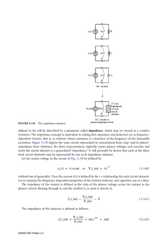
FIGURE 11.50 The impedance element.
defined so far will be described by a parameter called impedance, which may be viewed as a complex
resistance. The impedance concept is equivalent to stating that capacitors and inductors act as frequency-
dependent resistors, that is, as resistors whose resistance is a function of the frequency of the sinusoidal
excitation. Figure 11.50 depicts the same circuit represented in conventional form (top) and in phasor-
impedance form (bottom); the latter representation explicitly shows phasor voltages and currents and
treats the circuit element as a generalized “impedance.” It will presently be shown that each of the three
ideal circuit elements may be represented by one such impedance element.
Let the source voltage in the circuit of Fig. 11.50 be defined by
(
v S t() = Acos wt or V S jw) = Ae j0 ° (11.60)
without loss of generality. Then the current i(t) is defined by the i-v relationship for each circuit element.
Let us examine the frequency-dependent properties of the resistor, inductor, and capacitor, one at a time.
The impedance of the resistor is defined as the ratio of the phasor voltage across the resistor to the
phasor current flowing through it, and the symbol Z R is used to denote it:
V S jw)
(
Z R jw( ) = ------------------ = R (11.61)
(
I jw)
The impedance of the inductor is defined as follows:
V S jw) j90°
(
Z L jw( ) = ------------------ = wLe = jwL (11.62)
I jw)
(
©2002 CRC Press LLC