Page 229 - The Mechatronics Handbook
P. 229

0066_Frame_C11  Page 35  Wednesday, January 9, 2002  4:14 PM


                       In this example, we show that under certain conditions the impedance of the capacitor varies as a linear
                       function of displacement—that is, the movable-plate capacitor can serve as a linear transducer.
                         Recall the expression derived in Example 11.3:

                                                                   –
                                                                    3
                                                      C =  8.854 ×  10 A
                                                           ---------------------------------
                                                                x
                       where C is the capacitance in picofarad, A is the area of the plates in square millimeter, and x is the
                       (variable) distance in millimeter. If the capacitor is placed in an  AC circuit, its impedance will be
                       determined by the expression

                                                                1
                                                          Z C =  ----------
                                                               jwC
                       so that

                                                                x
                                                       Z C =  --------------------------
                                                            8.854 jw A
                       Thus, at a fixed frequency ω, the impedance of the capacitor will vary linearly with displacement. This
                       property may be exploited in the bridge circuit of Example 11.3, where a differential pressure transducer
                       was shown as being made of two movable-plate capacitors, such that if the capacitance of one increased
                       as a consequence of a pressure differential across the transducer, the capacitance of the other had to decrease
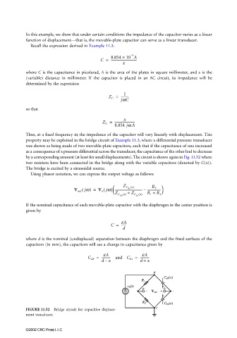
                       by a corresponding amount (at least for small displacements). The circuit is shown again in Fig. 11.52 where
                       two resistors have been connected in the bridge along with the variable capacitors (denoted by C(x)).
                       The bridge is excited by a sinusoidal source.
                         Using phasor notation, we can express the output voltage as follows:


                                                            
                                                                            R 2 
                                                                Z C ()
                                                                    x
                                              (
                                           V out jw) =  V S jw) ---------------------------------- –  ----------------- 
                                                        (
                                                                  bc
                                                            
                                                             Z C () +
                                                                          R 1 +
                                                                       x
                                                                      bc
                                                               db  x  Z C ()  R 2
                       If the nominal capacitance of each movable-plate capacitor with the diaphragm in the center position is
                       given by
                                                           C =  eA
                                                               ------
                                                                d
                       where d is the nominal (undisplaced) separation between the diaphragm and the fixed surfaces of the
                       capacitors (in mm), the capacitors will see a change in capacitance given by
                                                        eA
                                                                        eA
                                                 C db =  ----------- and C bc =  ------------
                                                       dx              d +  x
                                                        –


                       FIGURE 11.52  Bridge circuit for capacitive displace-
                       ment transducer.


                       ©2002 CRC Press LLC
   224   225   226   227   228   229   230   231   232   233   234