
Page 563 - The Mechatronics Handbook
P. 563
0066_Frame_C20 Page 33 Wednesday, January 9, 2002 5:49 PM
energy side of the device. Typically, an LED source is combined with either a phototransistor or photo
thyristor, see Fig. 20.35. In addition to signal isolation, optoisolators also help to reduce ground loop
issues between the logic and power side of the circuit.
Grounding
It is important to provide common ground among the different devices. For electromechanical actuators,
the high energy side is often switching at high frequency; if the ground point of the high energy side of
the circuit is directly connected to the ground of the low energy side of the circuit, switching noise may
propagate through the ground wire and negatively affect the operation of the low energy side of the
system. It is recommended that separate common grounds are established for the high and low energy
side and the two grounds are then connected at the power supply. In addition, an adequate-sized ground
plane needs to be provided to minimize the possibility of differences among grounding points.
20.2 Electrical Machines
C. J. Fraser
The utilization of electric motors as the power source in a mechatronic application is substantial. Electric
motors, therefore, often feature as the prime mover in a variety of driven systems. It is usually the
mechanical features of the application that determines the type of electric motor to be employed. The
torque–speed characteristics of the motor and the driven system are therefore very important. It is perhaps
then a paradox that while the torque–speed characteristics of the motor are readily available from the
supplier, the torque–speed characteristics of the driven system are often quite obscure.
The dc Motor
All conventional electric motors consist of a stationary element and a rotating element, which are separated
by an air gap. In dc motors, the stationary element consists of salient “poles,” which are constructed of
laminated assemblies with coils wound round them to produce a magnetic field. The function of the
laminations is to reduce the losses incurred by eddy currents. The rotating element is traditionally called
the “armature” and this consists of a series of coils located between slots around the periphery of the
armature. The armature is also fabricated in laminations, which are usually keyed onto a location shaft.
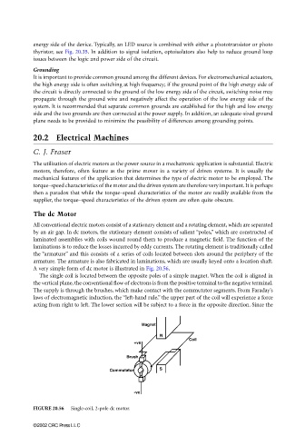
A very simple form of dc motor is illustrated in Fig. 20.56.
The single coil is located between the opposite poles of a simple magnet. When the coil is aligned in
the vertical plane, the conventional flow of electrons is from the positive terminal to the negative terminal.
The supply is through the brushes, which make contact with the commutator segments. From Faraday’s
laws of electromagnetic induction, the “left-hand rule,” the upper part of the coil will experience a force
acting from right to left. The lower section will be subject to a force in the opposite direction. Since the
Magnet
N
Coil
+ve
Brush
S
Commutator
-ve
FIGURE 20.56 Single-coil, 2-pole dc motor.
©2002 CRC Press LLC