
Page 561 - The Mechatronics Handbook
P. 561
0066_Frame_C20 Page 31 Wednesday, January 9, 2002 5:41 PM
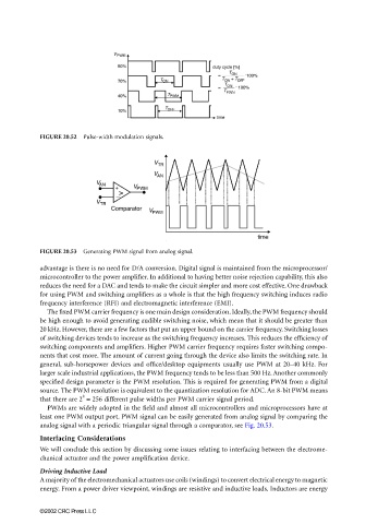
FIGURE 20.52 Pulse-width modulation signals.
FIGURE 20.53 Generating PWM signal from analog signal.
advantage is there is no need for D/A conversion. Digital signal is maintained from the microprocessor/
microcontroller to the power amplifier. In additional to having better noise rejection capability, this also
reduces the need for a DAC and tends to make the circuit simpler and more cost effective. One drawback
for using PWM and switching amplifiers as a whole is that the high frequency switching induces radio
frequency interference (RFI) and electromagnetic interference (EMI).
The fixed PWM carrier frequency is one main design consideration. Ideally, the PWM frequency should
be high enough to avoid generating audible switching noise, which mean that it should be greater than
20 kHz. However, there are a few factors that put an upper bound on the carrier frequency. Switching losses
of switching devices tends to increase as the switching frequency increases. This reduces the efficiency of
switching components and amplifiers. Higher PWM carrier frequency requires faster switching compo-
nents that cost more. The amount of current going through the device also limits the switching rate. In
general, sub-horsepower devices and office/desktop equipments usually use PWM at 20–40 kHz. For
larger scale industrial applications, the PWM frequency tends to be less than 500 Hz. Another commonly
specified design parameter is the PWM resolution. This is required for generating PWM from a digital
source. The PWM resolution is equivalent to the quantization resolution for ADC. An 8-bit PWM means
8
that there are 2 = 256 different pulse widths per PWM carrier signal period.
PWMs are widely adopted in the field and almost all microcontrollers and microprocessors have at
least one PWM output port. PWM signal can be easily generated from analog signal by comparing the
analog signal with a periodic triangular signal through a comparator, see Fig. 20.53.
Interfacing Considerations
We will conclude this section by discussing some issues relating to interfacing between the electrome-
chanical actuator and the power amplification device.
Driving Inductive Load
A majority of the electromechanical actuators use coils (windings) to convert electrical energy to magnetic
energy. From a power driver viewpoint, windings are resistive and inductive loads. Inductors are energy
©2002 CRC Press LLC