
Page 557 - The Mechatronics Handbook
P. 557
0066_Frame_C20 Page 27 Wednesday, January 9, 2002 5:41 PM
FIGURE 20.44 Variable gain voltage-mode amplifier.
FIGURE 20.45 Bipolar voltage-mode amplifier.
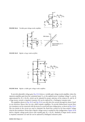
FIGURE 20.46 Bipolar variable gain voltage-mode amplifier.
To provide adjustable voltage gain, Fig. 20.44 shows a variable gain voltage-mode amplifier, where the
apparent amplifier gain from the command input V IN to the applied motor (winding) voltage V M can be
approximated by (R A + R B )/R A , which can be adjusted by proper selection of the resistors R A and R B . If
a large motor current is required, transistor Q2 can be replaced by a Darlington transistor pair.
The amplifiers shown in Fig. 20.43 and Fig. 20.44 can only drive the current through the motor (load)
in one direction. Hence, they are also called unipolar amplifiers. To provide bidirectional current flow,
two transistors can be connected with the motor in a push-pull type configuration, as shown in Fig. 20.45.
The two diodes in the circuit are used to eliminate the dead-zone created by the base-emitter voltage
drop for the transistors. Notice that a bipolar voltage source is needed for this configuration. Figure 20.46
shows a bipolar voltage-mode driver with variable gain (R A + R B )/R A . Similarly, if larger motor current
is required, transistors Q3 and Q4 can be replaced by Darlington transistor pairs.
©2002 CRC Press LLC