
Page 552 - The Mechatronics Handbook
P. 552
0066_Frame_C20 Page 22 Wednesday, January 9, 2002 5:41 PM
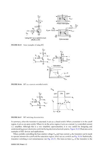
FIGURE 20.35 Some examples of using BJT.
FIGURE 20.36 BJT as a current controlled switch.
FIGURE 20.37 BJT switching characteristics.
In summary, when the transistor is saturated, it acts as a closed switch. When a transistor is in the cutoff
region, it acts as an open switch. When it is in the active region, it acts as a current (i B ) controlled current
(i C ) amplifier. Although this is a very simplistic approximation, it is very useful for designing and
understanding power electronics and interfacing electromechanical systems. Figure 20.35 illustrates some
examples of BJT devices and applications.
When carefully controlling the base-emitter voltage V BE and base current i B , the transistor can be made
to operate between the cutoff and the saturation region, which act as a switch, see Fig. 20.38. Realistically,
transistor switching is not instantaneous (see Fig. 20.37). The turn-on time t ON of the transistor is the
©2002 CRC Press LLC