
Page 548 - The Mechatronics Handbook
P. 548
0066_Frame_C20 Page 18 Wednesday, January 9, 2002 5:41 PM
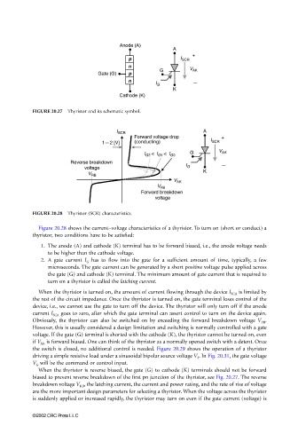
FIGURE 20.27 Thyristor and its schematic symbol.
FIGURE 20.28 Thyristor (SCR) characteristics.
Figure 20.28 shows the current–voltage characteristics of a thyristor. To turn on (short or conduct) a
thyristor, two conditions have to be satisfied:
1. The anode (A) and cathode (K) terminal has to be forward biased, i.e., the anode voltage needs
to be higher than the cathode voltage.
2. A gate current I G has to flow into the gate for a sufficient amount of time, typically, a few
microseconds. The gate current can be generated by a short positive voltage pulse applied across
the gate (G) and cathode (K) terminal. The minimum amount of gate current that is required to
turn on a thyristor is called the latching current.
When the thyristor is turned on, the amount of current flowing through the device I SCR is limited by
the rest of the circuit impedance. Once the thyristor is turned on, the gate terminal loses control of the
device, i.e., we cannot use the gate to turn off the device. The thyristor will only turn off if the anode
current I SCR goes to zero, after which the gate terminal can assert control to turn on the device again.
Obviously, the thyristor can also be switched on by exceeding the forward breakdown voltage V FB .
However, this is usually considered a design limitation and switching is normally controlled with a gate
voltage. If the gate (G) terminal is shorted with the cathode (K), the thyristor cannot be turned on, even
if V AK is forward biased. One can think of the thyristor as a normally opened switch with a detent. Once
the switch is closed, no additional control is needed. Figure 20.29 shows the operation of a thyristor
driving a simple resistive load under a sinusoidal bipolar source voltage V S . In Fig. 20.31, the gate voltage
V G will be the command or control input.
When the thyristor is reverse biased, the gate (G) to cathode (K) terminals should not be forward
biased to prevent reverse breakdown of the first pn junction of the thyristor, see Fig. 20.27. The reverse
breakdown voltage V RB , the latching current, the current and power rating, and the rate of rise of voltage
are the more important design parameters for selecting a thyristor. When the voltage across the thyristor
is suddenly applied or increased rapidly, the thyristor may turn on even if the gate current (voltage) is
©2002 CRC Press LLC