
Page 544 - The Mechatronics Handbook
P. 544
0066_Frame_C20 Page 14 Wednesday, January 9, 2002 5:41 PM
Vcc
FIGURE 20.19 DC motor under switching control.
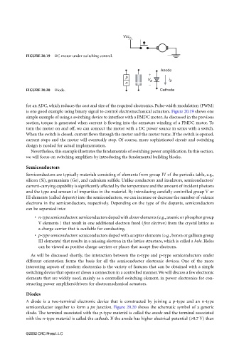
Anode
+
p
V D i D
n −
FIGURE 20.20 Diode. Cathode
for an ADC, which reduces the cost and size of the required electronics. Pulse-width modulation (PWM)
is one good example using binary signal to control electromechanical actuators. Figure 20.19 shows one
simple example of using a switching device to interface with a PMDC motor. As discussed in the previous
section, torque is generated when current is flowing into the armature winding of a PMDC motor. To
turn the motor on and off, we can connect the motor with a DC power source in series with a switch.
When the switch is closed, current flows through the motor and the motor turns. If the switch is opened,
current stops and the motor will eventually stop. Of course, more sophisticated circuit and switching
design is needed for actual implementation.
Nevertheless, this example illustrates the fundamentals of switching power amplification. In this section,
we will focus on switching amplifiers by introducing the fundamental building blocks.
Semiconductors
Semiconductors are typically materials consisting of elements from group IV of the periodic table, e.g.,
silicon (Si), germanium (Ge), and cadmium sulfide. Unlike conductors and insulators, semiconductors’
current-carrying capability is significantly affected by the temperature and the amount of incident photons
and the type and amount of impurities in the material. By introducing carefully controlled group V or
III elements (called dopants) into the semiconductors, we can increase or decrease the number of valence
electrons in the semiconductors, respectively. Depending on the type of the dopants, semiconductors
can be separated into:
• n-type semiconductors: semiconductors doped with donor elements (e.g., arsenic or phosphor group
V elements ) that result in one additional electron freed (free electron) from the crystal lattice as
a charge carrier that is available for conducting.
• p-type semiconductors: semiconductors doped with acceptor elements (e.g., boron or gallium group
III elements) that results in a missing electron in the lattice structure, which is called a hole. Holes
can be viewed as positive charge carriers or places that accept free electrons.
As will be discussed shortly, the interaction between the n-type and p-type semiconductors under
different orientation forms the basis for all the semiconductor electronic devices. One of the more
interesting aspects of modern electronics is the variety of features that can be obtained with a simple
switching device that opens or closes a connection in a controlled manner. We will discuss a few electronic
elements that are widely used, mainly as a controlled switching element, in power electronics for con-
structing power amplifiers/drivers for electromechanical actuators.
Diodes
A diode is a two-terminal electronic device that is constructed by joining a p-type and an n-type
semiconductor together to form a pn junction. Figure 20.20 shows the schematic symbol of a generic
diode. The terminal associated with the p-type material is called the anode and the terminal associated
with the n-type material is called the cathode. If the anode has higher electrical potential (>0.7 V) than
©2002 CRC Press LLC