
Page 540 - The Mechatronics Handbook
P. 540
0066_Frame_C20 Page 10 Wednesday, January 9, 2002 5:41 PM
Commutator is the part of the DC motor rotor that is in contact with the brushes and is used for
controlling the armature current direction. Commutation can be interpreted as the method to control
the current directions in the stator and/or the armature coils so that a desired relative stator and rotor
magnetic flux direction is maintained. For AC motors, commutation is done by the AC applied current
as well as the design of the winding geometry. For stepping motors and brushless DC (BLDC) motors,
commutations are done in the drive electronics and/or motor commands.
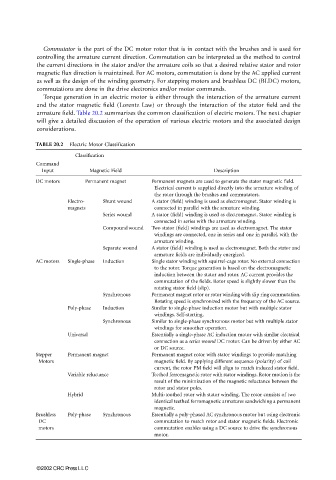
Torque generation in an electric motor is either through the interaction of the armature current
and the stator magnetic field (Lorentz Law) or through the interaction of the stator field and the
armature field. Table 20.2 summarizes the common classification of electric motors. The next chapter
will give a detailed discussion of the operation of various electric motors and the associated design
considerations.
TABLE 20.2 Electric Motor Classification
Classification
Command
Input Magnetic Field Description
DC motors Permanent magnet Permanent magnets are used to generate the stator magnetic field.
Electrical current is supplied directly into the armature winding of
the rotor through the brushes and commutators.
Electro- Shunt wound A stator (field) winding is used as electromagnet. Stator winding is
magnets connected in parallel with the armature winding.
Series wound A stator (field) winding is used as electromagnet. Stator winding is
connected in series with the armature winding.
Compound wound Two stator (field) windings are used as electromagnet. The stator
windings are connected, one in series and one in parallel, with the
armature winding.
Separate wound A stator (field) winding is used as electromagnet. Both the stator and
armature fields are individually energized.
AC motors Single-phase Induction Single stator winding with squirrel-cage rotor. No external connection
to the rotor. Torque generation is based on the electromagnetic
induction between the stator and rotor. AC current provides the
commutation of the fields. Rotor speed is slightly slower than the
rotating stator field (slip).
Synchronous Permanent magnet rotor or rotor winding with slip ring commutation.
Rotating speed is synchronized with the frequency of the AC source.
Poly-phase Induction Similar to single-phase induction motor but with multiple stator
windings. Self-starting.
Synchronous Similar to single-phase synchronous motor but with multiple stator
windings for smoother operation.
Universal Essentially a single-phase AC induction motor with similar electrical
connection as a series wound DC motor. Can be driven by either AC
or DC source.
Stepper Permanent magnet Permanent magnet rotor with stator windings to provide matching
Motors magnetic field. By applying different sequence (polarity) of coil
current, the rotor PM field will align to match induced stator field.
Variable reluctance Teethed ferromagnetic rotor with stator windings. Rotor motion is the
result of the minimization of the magnetic reluctance between the
rotor and stator poles.
Hybrid Multi-toothed rotor with stator winding. The rotor consists of two
identical teethed ferromagnetic armatures sandwiching a permanent
magnetic.
Brushless Poly-phase Synchronous Essentially a poly-phased AC synchronous motor but using electronic
DC commutation to match rotor and stator magnetic fields. Electronic
motors commutation enables using a DC source to drive the synchronous
motor.
©2002 CRC Press LLC