
Page 538 - The Mechatronics Handbook
P. 538
0066_Frame_C20 Page 8 Wednesday, January 9, 2002 5:41 PM
TABLE 20.1 Temprature Rating For Electrical Insulations
Insulation Classification Temperature Rating
Class A Class 105 105°C 221°F
Class E Class 120 120°C 248°F
Class B Class 130 130°C 266°F
Class F Class 155 155°C 311°F
Class H Class 180 180°C 356°F
Class N Class 200 200°C 392°F
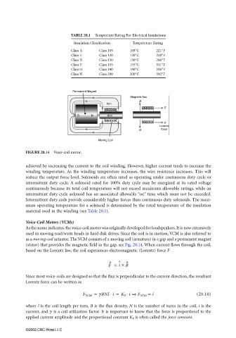
FIGURE 20.14 Voice-coil motor.
achieved by increasing the current to the coil winding. However, higher current tends to increase the
winding temperature. As the winding temperature increases, the wire resistance increases. This will
reduce the output force level. Solenoids are often rated as operating under continuous duty cycle or
intermittent duty cycle. A solenoid rated for 100% duty cycle may be energized at its rated voltage
continuously because its total coil temperature will not exceed maximum allowable ratings, while an
intermittent duty cycle solenoid has an associated allowable “on” time which must not be exceeded.
Intermittent duty coils provide considerably higher forces than continuous duty solenoids. The maxi-
mum operating temperature for a solenoid is determined by the rated temperature of the insulation
material used in the winding (see Table 20.1).
Voice-Coil Motors (VCMs)
As the name indicates, the voice-coil motor was originally developed for loudspeakers. It is now extensively
used in moving read/write heads in hard disk drives. Since the coil is in motion, VCM is also referred to
as a moving-coil actuator. The VCM consists of a moving coil (armature) in a gap and a permanent magnet
(stator) that provides the magnetic field in the gap, see Fig. 20.14. When current flows through the coil,
based on the Lorentz law, the coil experiences electromagnetic (Lorentz) force F
F = i × B
Since most voice-coils are designed so that the flux is perpendicular to the current direction, the resultant
Lorentz force can be written as
F VCM = γ BNl i = K F i ⇒ F VCM ∝ i (20.10)
⋅
⋅
where l is the coil length per turn, B is the flux density, N is the number of turns in the coil, i is the
current, and γ is a coil utilization factor. It is important to know that the force is proportional to the
applied current amplitude and the proportional constant K F is often called the force constant.
©2002 CRC Press LLC