
Page 539 - The Mechatronics Handbook
P. 539
0066_Frame_C20 Page 9 Wednesday, January 9, 2002 5:41 PM
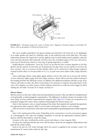
FIGURE 20.15 Permanent magnet DC motor. (T. Keujo and S. Nagamori, Permanent-Magnet and Brushless DC
Motors, 1985, by permission of Oxford University Press.)
The coil is usually suspended in the gap by springs and attached to the load such as the diaphragm
of an audio speaker, the spool of a hydraulic valve, or the read/write head of the disk drive. The linear
relationship between the output force and the applied current and the bidirectional capability makes the
voice coil more attractive than solenoids. However, since the controlled output of the voice coil is force,
some type of closed loop control or some type of spring suspension is needed.
Design/Selection Consideration. From Eq. (20.10) we see that the force constant depends on the flux
density and the amount of wires that can be packed into the gap. There are two options to increase the
force constant. One is to increase the flux density, which can be achieved by using stronger magnetic
material and the other is to increase either N or l, i.e., to pack more turns and/or make a larger diameter
coil.
Given a fixed gap volume, using higher gauge (thinner) wires is the only way to increase the number
of turns. However, higher gauge wires have larger resistance, which will increase the resistive heating of
the winding and limit the allowable current. In addition, the additional insulation will also occupy more
volume and tends to reduce the effect of increasing N. In summary, to improve the performance of the
voice coil, a designer can either choose a better magnetic material or to make the motor bigger by either
making the coil wider (increase D) or longer (increase N).
Electric Motors
Electric motors are the most widely used electromechanical actuators. They can either be classified based
on functionality or electromagnetic characteristics. The differences in electric motors are mainly in the
rotor design and the method of generating the magnetic field. Figure 20.17 shows the composition of a
permanent magnet DC motor. Some common terminologies for electric motors are:
Stator is the stationary outer or inner housing of the motor that supports the material that generates
the appropriate stator magnetic field. It can be made of permanent magnet or coil windings.
Field coil (system) is the portion of the stator that is responsible for generating the stator (field) magnetic
flux.
Rotor is the rotating part of the motor. Depending on the construction, it can be a permanent magnet
or a ferromagnetic core with coil windings (armature) to provide the appropriate armature field to
interact with the stator field to create the torque.
Armature is the rotor winding that carries current and induces a rotor magnetic field.
Air gap is the small gap between the rotor and the stator, where the two magnetic fields interact and
generate the output torque.
Brush is the part of a DC motor through which the current is supplied to the armature (rotor). For
synchronous AC motors, this is done by slip rings.
©2002 CRC Press LLC