
Page 542 - The Mechatronics Handbook
P. 542
0066_Frame_C20 Page 12 Wednesday, January 9, 2002 5:41 PM
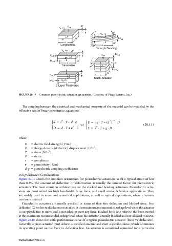
FIGURE 20.17 Common piezoelectric actuation geometries. (Courtesy of Piezo Systems, Inc.)
The coupling between the electrical and mechanical property of the material can be modeled by the
following sets of linear constitutive equations:
T −1
⋅
S = s ⋅ T + d E E = −gT +⋅ ε () ⋅ D
E
⇔ (20.11)
⋅
⋅
T
D = d T + ε ⋅ E S = s ⋅ T + g D
D
where
E = electric field strength [V/m]
2
D = charge-density (dielectric) displacement [C/m ]
2
T = stress [N/m ]
S = strain
s = compliance
ε = permittivity [F/m]
d, g = piezoelectric coupling coefficients
Design/Selection Considerations
Figure 20.17 shows the common orientation for piezoelectric actuation. With a typical strain of less
than 0.3%, the amount of deflection or deformation is usually the limited factor for piezoelectric
actuators. The most common architectures are the stacked and bending actuation. Piezoelectric actu-
ators are most suited for high bandwidth, large force, and small stroke/deflection applications. They
are widely used in noise and acoustical applications, as well as optical applications, where precision
motion is critical.
Piezoelectric actuators are usually specified in terms of their free deflection and blocked force. Free
deflection (X f ) refers to displacement attained at the maximum recommended voltage level when the actuator
is completely free to move and is not asked to exert any force. Blocked force (F b ) refers to the force exerted
at the maximum recommended voltage level when the actuator is totally blocked and not allowed to move.
Figure 20.18 shows the static performance curve of a typical piezoelectric actuator (force vs. deflection).
Generally, a piezo actuator must deform a specified amount and exert a specified force, which determines
its operating point on the force vs. deflection line. An actuator is considered optimized for a particular
©2002 CRC Press LLC