
Page 537 - The Mechatronics Handbook
P. 537
0066_Frame_C20 Page 7 Wednesday, January 9, 2002 5:41 PM
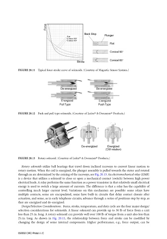
FIGURE 20.11 Typical force-stroke curve of solenoids. (Courtesy of Magnetic Sensor Systems.)
FIGURE 20.12 Push and pull type solenoids. (Courtesy of Ledex® & Dormeyer® Products.)
FIGURE 20.13 Rotary solenoid. (Courtesy of Ledex® & Dormeyer® Products.)
Rotary solenoids utilize ball bearings that travel down inclined raceways to convert linear motion to
rotary motion. When the coil is energized, the plunger assembly is pulled towards the stator and rotated
through an arc determined by the coining of the raceways, see Fig. 20.13. An electromechanical relay (EMR)
is a device that utilizes a solenoid to close or open a mechanical contact (switch) between high power
electrical leads. A relay performs the same function as a power transistor in that relatively small electrical
energy is used to switch a large amount of currents. The difference is that a relay has the capability of
controlling much larger current level. Variations on this mechanism are possible: some relays have
multiple contacts, some are encapsulated, some have built-in circuits that delay contact closure after
actuation, and some, as in early telephone circuits, advance through a series of positions step by step, as
they are energized and de-energized.
Design/Selection Considerations. Force, stroke, temperature, and duty cycle are the four major design/
selection considerations for solenoids. A linear solenoid can provide up to 30 lb of force from a unit
1
less than 2 / 4 in. long. A rotary solenoid can provide well over 100 lb of torque from a unit also less than
1
2 / 4 in. long. As shown in Fig. 20.11, the relationship between force and stroke can be modified by
changing the design of some internal components. Higher performance, e.g., force output, can be
©2002 CRC Press LLC