
Page 536 - The Mechatronics Handbook
P. 536
0066_Frame_C20 Page 6 Wednesday, January 9, 2002 5:41 PM
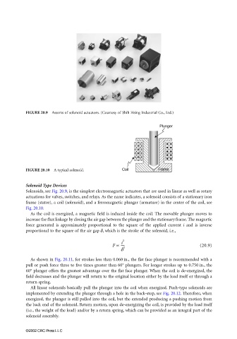
FIGURE 20.9 Assorts of solenoid actuators. (Courtesy of Shih Hsing Industrial Co., Ltd.)
FIGURE 20.10 A typical solenoid.
Solenoid Type Devices
Solenoids, see Fig. 20.9, is the simplest electromagnetic actuators that are used in linear as well as rotary
actuations for valves, switches, and relays. As the name indicates, a solenoid consists of a stationary iron
frame (stator), a coil (solenoid), and a ferromagnetic plunger (armature) in the center of the coil, see
Fig. 20.10.
As the coil is energized, a magnetic field is induced inside the coil. The movable plunger moves to
increase the flux linkage by closing the air gap between the plunger and the stationary frame. The magnetic
force generated is approximately proportional to the square of the applied current i and is inverse
proportional to the square of the air gap δ, which is the stroke of the solenoid, i.e.,
i
F ∝ ---- 2 (20.9)
δ 2
As shown in Fig. 20.11, for strokes less than 0.060 in., the flat face plunger is recommended with a
pull or push force three to five times greater than 60° plungers. For longer strokes up to 0.750 in., the
60° plunger offers the greatest advantage over the flat face plunger. When the coil is de-energized, the
field decreases and the plunger will return to the original location either by the load itself or through a
return spring.
All linear solenoids basically pull the plunger into the coil when energized. Push-type solenoids are
implemented by extending the plunger through a hole in the back-stop, see Fig. 20.12. Therefore, when
energized, the plunger is still pulled into the coil, but the extended producing a pushing motion from
the back end of the solenoid. Return motion, upon de-energizing the coil, is provided by the load itself
(i.e., the weight of the load) and/or by a return spring, which can be provided as an integral part of the
solenoid assembly.
©2002 CRC Press LLC