
Page 547 - The Mechatronics Handbook
P. 547
0066_Frame_C20 Page 17 Wednesday, January 9, 2002 5:41 PM
used, diode array can be used. In general, the term diode array implies four or more diodes in a single
package. The most efficient packaging scheme is typically eight diodes or more in a dual inline package
(DIP). Other packages are the single inline package (SIP), the flat pack, and even a surface mount
diode array. Although multiple diode arrays can incorporate different type diodes, the most popular
arrays incorporate a fast, small signal diode such as the 1N4148, and the core driver arrays, which employ
a fast switching, higher current, 100-mA diode.
Zener Diode
Recall the current–voltage curve of a diode shown in Fig. 20.21. −
If a diode is reverse biased to the breakdown region, a large + + V D
reverse current will flow through the diode. For most diodes,
this voltage is usually larger than 50 V and may exceed kilovolts.
Zener (Avalanche) diodes are a class of diodes that exhibit a steep
breakdown curve with a well-defined reverse breakdown voltage
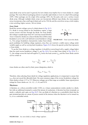
FIGURE 20.25 Zener (avalanche) diode.
V Z . This unique breakdown characteristic makes Zener diodes
good candidates for building voltage regulators, since they can maintain a stable source voltage under
variable supply as well as varying load impedance. Figure 20.25 shows the special symbol that represents
a Zener diode.
To use the Zener diode as a voltage regulator, it should be reverse biased with a supply voltage higher
than the rated reverse breakdown voltage V Z , see Fig. 20.26. For an ideal Zener diode, in Fig. 20.26, V S >
V Z , the voltage across the load will equal to V Z ; hence the load current i load and the Zener diode current
can be written as
V S – V Z
i load = ---------- and i Z = ------------------ .
V Z
R load R S
Zener diodes are often rated by their power dissipation, which is
P Zmax = i Zmax V Z .
⋅
Therefore, when selecting Zener diode for voltage regulation applications, it is important to ensure that
i Zmax does not exceed the allowable limit. The most common range of the reverse breakdown voltage for
Zener diodes is from 3.3 V to 75 V. However, voltages out of this range are available. Some typical power
ratings for Zener diodes are 1/4, 1/2, 1, 5, 10, and 50 W.
Thyristors
A thyristor, or a silicon-controlled rectifier (SCR), is a 4-layer semiconductor switch, similar to a diode,
but with an additional terminal to control the instant of conduction. A thyristor has three terminals: an
anode, a cathode, and a gate, see Fig. 20.27. One can think of a thyristor as a controllable diode that the
gate terminal provides as a mean of precise control of the instance when the thyristor is to be turned on,
i.e., it is a controlled switch.
Unregulated Voltage
Source Regulator
R S Load
i L
+
V S + + + i S i Z V Z R L
- - - - -
-
-
FIGURE 20.26 Use zener diode as simple voltage regulator.
©2002 CRC Press LLC