
Page 556 - The Mechatronics Handbook
P. 556
0066_Frame_C20 Page 26 Wednesday, January 9, 2002 5:41 PM
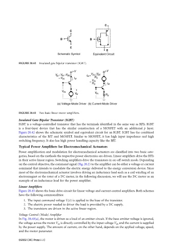
FIGURE 20.42 Insulated gate bipolar transistor (IGBT).
FIGURE 20.43 Two basic linear motor amplifiers.
Insulated Gate Bipolar Transistor (IGBT)
IGBT is a voltage-controlled transistor that has the terminals identified in the same way as BJTs. IGBT
is a four-layer device that has the similar construction of a MOSFET with an additional p layer.
Figure 20.42 shows the schematic symbol and equivalent circuit for an IGBT. IGBT has the combined
characteristics of the BJT and MOSFET. Similar to MOSFET, it has high input impedance and high
switching frequency. It also has high power handling capacity like the BJT.
Typical Power Amplifiers for Electromechanical Actuators
Power amplification and modulation for electromechanical actuators are classified into two basic cate-
gories, based on the methods the respective power electronics are driven. Linear amplifiers drive the BJTs
in their active linear region. Switching amplifiers drive the transistors in on-off switch mode. Depending
on the control objective, the command signal (Fig. 20.2) to the amplifier can be either a voltage or current
command that intends to modulate the electric energy delivered to the energy conversion device. Since
most of the electromechanical actuator involves driving an inductance load such as a coil winding of an
electromagnet or the rotor of a DC motor, in the following discussion, we will use the DC motor as an
example of an inductance load for the power amplifier.
Linear Amplifiers
Figure 20.43 shows the basic drive circuit for linear voltage and current control amplifiers. Both schemes
have the following commonalities:
1. The input command voltage V i (t) is applied to the base of the transistor.
2. The electric power needed to driver the load is provided by a DC supply.
3. The transistors are driven in the active linear region.
Voltage Control (Mode) Amplifier
In Fig. 20.43(a), the motor is driven as a load of an emitter circuit. If the base-emitter voltage is ignored,
the voltage across the motor V M is directly controlled by the input voltage V IN and the current is supplied
by the power supply. The amount of current, on the other hand, depends on the applied voltage, speed,
and the motor parameter.
©2002 CRC Press LLC