
Page 560 - The Mechatronics Handbook
P. 560
0066_Frame_C20 Page 30 Wednesday, January 9, 2002 5:41 PM
FIGURE 20.50 Switching push-pull amplifier.
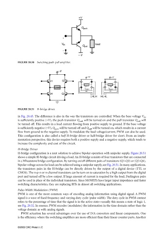
FIGURE 20.51 H-bridge driver.
in Fig. 20.45. The difference is also in the way the transistors are controlled. When the base voltage V IN
is sufficiently positive (+V), the push transistor Q push will be turned on and the pull transistor Q pull will
be turned off. This results in a load current flowing from positive supply to ground. If the base voltage
is sufficiently negative (−V), Q push will be turned off and Q pull will be turned on, which results in a current
flow from ground to the negative supply. To modulate the load voltage/current, PWM can also be used.
This configuration is also called a half H-bridge driver or half-bridge driver for short. From an imple-
mentation perspective, this device requires both a positive supply and a negative supply, which tends to
increase the complexity and cost of the circuit.
H-Bridge Driver
H-bridge configuration is a neat solution to achieve bipolar operation with unipolar supply. Figure 20.51
shows a simple H-bridge circuit driving a load. An H-bridge consists of four transistors that are connected
in a Wheatstone bridge configuration. By turning on/off different pairs of transistors (Q1-Q3) or (Q2-Q4),
bipolar voltage across the load can be achieved using a unipolar supply, see Fig. 20.51. In many applications,
the transistors pairs in the H-bridge can be directly driven by the output of a digital device (TTL or
CMOS). The n-p-n or n-channel transistors can be turn on to saturation by a high output from the digital
port and turned off by a low output. If large amount of current is required for the load, Darlington pairs
can be used in place of the individual transistors. Since MOSFETs have larger input impedance and faster
switching characteristics, they are replacing BJTs in almost all switching applications.
Pulse-Width Modulation (PWM)
PWM is one of the more common ways of encoding analog information using digital signal. A PWM
signal is a wave of fixed frequency and varying duty cycle (pulse width). The duty cycle in PWM context
refers to the percentage of time that the signal is in the active state—usually this means a state of logic 1,
see Fig. 20.52. In essence, PWM encodes (modulates) the information in the time domain rather than the
voltage domain as with analog signals.
PWM actuation has several advantages over the use of D/A converters and linear components. One
is the efficiency where the switching amplifiers are more efficient than their linear counter parts. Another
©2002 CRC Press LLC