
Page 562 - The Mechatronics Handbook
P. 562
0066_Frame_C20 Page 32 Wednesday, January 9, 2002 5:41 PM
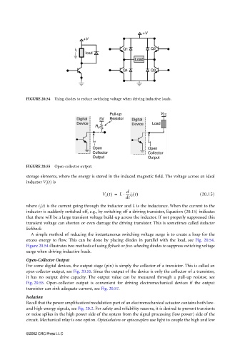
FIGURE 20.54 Using diodes to reduce swithcing voltage when driving inductive loads.
FIGURE 20.55 Open-collector output.
storage elements, where the energy is stored in the induced magnetic field. The voltage across an ideal
inductor V I (t) is
d
⋅
V I t() = L -----i I t() (20.15)
dt
where i I (t) is the current going through the inductor and L is the inductance. When the current to the
inductor is suddenly switched off, e.g., by switching off a driving transistor, Equation (20.15) indicates
that there will be a large transient voltage build-up across the inductor. If not properly suppressed this
transient voltage can shorten or even damage the driving transistor. This is sometimes called inductor
kickback.
A simple method of reducing the instantaneous switching voltage surge is to create a loop for the
excess energy to flow. This can be done by placing diodes in parallel with the load, see Fig. 20.54.
Figure 20.54 illustrates two methods of using flyback or free-wheeling diodes to suppress switching voltage
surge when driving inductive loads.
Open-Collector Output
For some digital devices, the output stage (pin) is simply the collector of a transistor. This is called an
open-collector output, see Fig. 20.55. Since the output of the device is only the collector of a transistor,
it has no output drive capacity. The output value can be measured through a pull-up resistor, see
Fig. 20.55. Open-collector output is convenient for driving electromechanical devices if the output
transistor can sink adequate current, see Fig. 20.57.
Isolation
Recall that the power amplification/modulation part of an electromechanical actuator contains both low-
and high-energy signals, see Fig. 20.2. For safety and reliability reasons, it is desired to prevent transients
or noise spikes in the high power side of the system from the signal processing (low power) side of the
circuit. Mechanical relay is one option. Optoisolators or optocouplers use light to couple the high and low
©2002 CRC Press LLC