
Page 897 - The Mechatronics Handbook
P. 897
0066_Frame_C30 Page 8 Thursday, January 10, 2002 4:43 PM
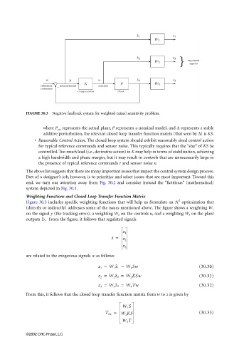
FIGURE 30.3 Negative feedback system for weighted mixed sensitivity problem.
where P act represents the actual plant, P represents a nominal model, and ∆ represents a stable
additive perturbation, the relevant closed loop transfer function matrix (that seen by ∆) is KS.
• Reasonable Control Action. The closed loop system should exhibit reasonably sized control action
for typical reference commands and sensor noise. This typically requires that the “size” of KS be
controlled. Too much lead (i.e., derivative action) in K may help in terms of stabilization, achieving
a high bandwidth and phase margin, but it may result in controls that are unnecessarily large in
the presence of typical reference commands r and sensor noise n.
The above list suggests that there are many important issues that impact the control system design process.
Part of a designer’s job, however, is to prioritize and select issues that are most important. Toward this
end, we turn our attention away from Fig. 30.2 and consider instead the “fictitious” (mathematical)
system depicted in Fig. 30.3.
Weighting Functions and Closed Loop Transfer Function Matrix
2
Figure 30.3 includes specific weighting functions that will help us formulate an H optimization that
(directly or indirectly) addresses some of the issues mentioned above. The figure shows a weighting W 1
on the signal y (the tracking error), a weighting W 2 on the controls u, and a weighting W 3 on the plant
outputs z ˆ 3. From the figure, it follows that regulated signals
z 1
z =
z 2
z 3
are related to the exogenous signals w as follows:
z 1 = W 1 z ˆ 1 = W 1 Sw (30.30)
z 2 = W 2 z ˆ 2 = W 2 KSw (30.31)
z 3 = W 3 z ˆ 3 = W 3 Tw (30.32)
From this, it follows that the closed loop transfer function matrix from w to z is given by
W 1 S
T wz = W 2 KS (30.33)
W 3 T
©2002 CRC Press LLC