Page 898 - The Mechatronics Handbook
P. 898
0066_Frame_C30  Page 9  Thursday, January 10, 2002  4:43 PM


                       Since T wz  involves various “sensitivity” transfer function matrices, we say that we have a weighted mixed
                       sensitivity problem.

                       Selection of Weighting Functions
                       Typically, the weighting functions W 1 , W 2 , W 3  are selected to be stable transfer function matrices that
                       are (at least initially) diagonally structured.
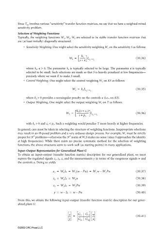
                          • Sensitivity Weighting. One might select the sensitivity weighting W 1  on the sensitivity S as follows:


                                                      W 1 =  ---------- I n ×                   (30.34)
                                                              k 1
                                                             s +  e  y  n y
                            where k 1 ,   > 0. The parameter k 1  is typically selected to be large. The parameter   is typically
                            selected to be small. Such selections are made so that S is heavily penalized at low frequencies—
                            precisely where we want K to make S small.
                          • Control Weighting. One might select the control weighting W 2  on KS as follows:

                                                        W 2 =  k 2 I n ×                        (30.35)
                                                                 u  n u

                            where k 2  > 0 provides a nonsingular penalty on the controls u (i.e., on KS).
                          • Output Weighting. One might select the output weighting W 3  on T as follows:

                                                           k 3 s +  z 3 )
                                                             (
                                                    W 3 =  ---------------------- I n ×         (30.36)
                                                            s +  p 3  y  n y

                            with k 3  > 0 and z 3  < p 3 . Such a weighting would penalize T more heavily at higher frequencies.
                       In general, care must be taken in selecting the structure of weighting functions. Inappropriate selections
                       may result in an ill-posed problem and a very arduous design process. For example, W 1  must be strictly
                                2                      2
                       proper for H   problems—otherwise the H  norm of W 1 S makes no sense (since S approaches the identity
                       at high frequencies).  While there exists no precise systematic method for the selection of weighting
                       functions, the above structures seem to work well (as starting points) in many applications.
                       Input–Output Representation for Generalized Plant G
                       To obtain an input–output (transfer function matrix) description for our generalized plant, we must
                       express the regulated signals z 1 , z 2 , z 3  and the measurements y in terms of the exogenous signals w and
                       the controls u. Doing so yields

                                                           (
                                            z 1 =  W 1 z ˆ 1 =  W 1 wPu) =  W 1 wW 1 Pu         (30.37)
                                                             –
                                                                         –
                                            z 2 =  W 2 z ˆ 2 =  W 2 u                           (30.38)
                                            z 3 =  W 3 z ˆ 3 =  W 3 Pu                          (30.39)

                                             y =  w z ˆ 3 =  wPu                                (30.40)
                                                           –
                                                   –
                       From this, we obtain the following input–output (transfer function matrix) description for our gener-
                       alized plant G:


                                                      z  =  G 11 G 12 w                         (30.41)
                                                      y     G 21 G 22 u


                       ©2002 CRC Press LLC

