Page 980 - The Mechatronics Handbook
P. 980

x


                                 FIGURE 33.4  Closed loop-position control with indirect measurement.

                                                        Other Users        Servovalve  (Servo)  Cylinder
                                                                                     Q M2A
                                                     p = konst.                      p M2A
                                                                          P     A
                                                                           T    B
                                                                                     Q M2B
                                                                                     p M2B
                                          Accumulator
                                                                                                    y, v, a
                                                                                                 F L
                                          High Pressure Filter                        Q M1A
                                                        Q                             p M1A
                                                         P
                                                                                              ϕ, ω, α
                                                     ω P
                                                                           ε U
                                                                              - U actual
                                                                            Σ                    M L
                                                                                        Q M1B
                                                                             U prescribed  p M1B
                                            Tank
                                                                   Return Line Filter  Tacho Generator  Tank
                                           Electro Motor   Pressure Reduction Valve  Servovalve  (Servo)  Rotary Motor  Load
                                                      Variable Displacement Pump
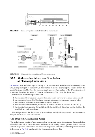
                                 FIGURE 33.5  Volumetric Q-rate regulation with constant pressure.
                                 33.3 Mathematical Model and Simulation
                                         of Electrohydraulic Axes


                                 Section 33.3 deals with the analytical findings of the mathematical model (MM) of an electrohydraulic
                                 axis, a component part of robot ROBI_3. This method of analysis is advantageous because it offers the
                                 possibility to use this MM for other electrohydraulic axes as well, regardless of the different number of
                                 stages, and also allows the testing of dynamic performances of the axis at the design level.
                                   In this section, the following were realized:
                                    1. the static models of electrohydraulic system components (servovalve, hydraulic linear motor);
                                    2. the parameters involved in MM, based on constructive and flowing regime characteristics;
                                    3. the nonlinear MM of the proposed electrohydraulic system;
                                    4. the structural scheme of the hydraulic axis in order to simulate its behavior (SIMULINK);
                                    5. the investigations regarding MM, which certify the stability of the system and the fact that the
                                       modelled process is a rapid one.
                                   Values of parameters that describe the MM are set based on hydraulic characteristics and on construc-
                                 tive parameters of the considered system.

                                 The Extended Mathematical Model
                                 The studied system consists of a servovalve and an asymmetric motor. In most cases, the control of an
                                 electrohydraulic axis is directed towards position control, velocity control, pressure control, or force
                                 control. The position control of the axis is studied. The position control loop for the proposed installation
                                 is illustrated in Fig. 33.6, together with the denomination of some data.

                                 ©2002 CRC Press LLC
   975   976   977   978   979   980   981   982   983   984   985