
Page 983 - The Mechatronics Handbook
P. 983
0066_frame_Ch33.fm Page 7 Wednesday, January 9, 2002 8:00 PM
N
F c1 F p A
p A f B R
A K
F d1
F T
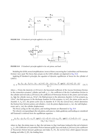
FIGURE 33.8 D’Alembert’s principle applied to the cylinder.
. ..
x,x,x
F f
p A p A
B R
A K
F L
F T
N 3
F f3
FIGURE 33.9 D’Alembert’s principle applied to the rod, piston, and load.
Modeling the LHM, several simplifications (most of them concerning the Coulombian and Newtonian
friction) were used. The forces that actuate on the LHM cylinder are depicted in Fig. 33.8:
Applying D’Alembert’s principle, the equation of dynamic equilibrium of forces for the cylinder of
LHM is
.
(
.
.
.
.
.
–
–
x ˙ 2 = p B A R – p A A k + c 1 ( x 1 – x 2 ) + d 1 . ˙ 1 –( x x ˙ 2) + c fu N sgn x ˙ x ˙ 2) + d z ( x ˙ x ˙ 2) (33.7)
-----------------------------------------------------------------------------------------------------------------------------------------------------------------------------------------------
.
m 2 s
where c 1 [N/m], the elasticity; d 1 [N/(m/s)], the linearized coefficient of the viscous Newtonian friction
in the connection actuators’ cylinder and wall; c fu [-], the coefficient of the dry Coulombian friction in
the cylinder and rod seals; d z [N/(m/s)], the coefficient of Newtonian friction in the piston and rod seals;
2
m 2 [kg], the cylinder mass; p A [N/m ], the fluid pressure in the admission chamber A of the actuator; p B
2
2
[N/m ], the fluid pressure in the discharge chamber B of the actuator; A K [m ], the piston active area in
2
chamber A; A R [m ], the piston active area in chamber B; N [N], the normal force, which determines
the friction force between piston and cylinder; x [m], the piston displacement; x 1 [m], the wall displace-
ment; and x 2 [m], the cylinder displacement.
The forces acting on the rod, piston, and working element are illustrated in Fig. 33.9
The velocity corresponding to the rod, piston, and mass m 3 (slade, guideway, and loading are considered
stiff fastened) is inferred from the equilibrium equation:
(
(
(
(
.
.
. .
.
.
.
.
–
–
–
–
–
–
–
–
–
x ˙ = p A A K – p B A R F L c fu N sgn x ˙ x ˙ 2) d z x ˙ x ˙ 2) c fu3 N 3 sgn x ˙ x ˙ 1) d 3 x ˙ x ˙ 1) (33.8)
-------------------------------------------------------------------------------------------------------------------------------------------------------------------------------------------------------------
( m p + m T + m 3 )⋅s
where m p [kg], the piston mass; m T [kg], the rod mass; m 3 [kg], load mass (reduced at the rod of piston);
c fu3 [-], the coefficient of Coulombian friction between guide ways and slade; d 3 [N/(m/s)], the coefficient
of Newtonian friction between guideways and slade; N 3 [N], the normal force which appears between
loading and table; F L [N], the loading force.
©2002 CRC Press LLC