
Page 986 - The Mechatronics Handbook
P. 986
0066_frame_Ch33.fm Page 10 Wednesday, January 9, 2002 8:00 PM
U ref + e I Q y
Σ K UI x
_ H sv H zyl
U
k
. _
^
^
x x y ^
b ∫ c T
Observer A
Contro-
ller R
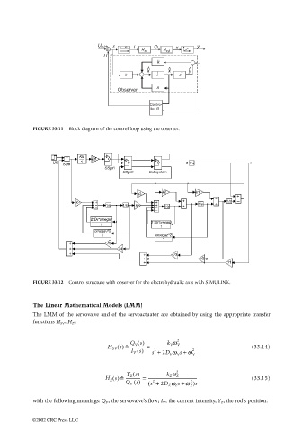
FIGURE 33.11 Block diagram of the control loop using the observer.
FIGURE 33.12 Control structure with observer for the electrohydraulic axis with SIMULINK.
The Linear Mathematical Models (LMM)
The LMM of the servovalve and of the servoactuator are obtained by using the appropriate transfer
functions H SV , H Z :
Q V s() 2
k V w V
H SV s() = ˆ -------------- = ------------------------------------------ (33.14)
I V s() s + 2D V w V s w V 2
+
2
Y Z s() 2
H Z s() = ˆ --------------- = ------------------------------------------------- (33.15)
k Z w Z
Q V s() ( s + 2D Z w Z s w Z )s
+
2
2
with the following meanings: Q V , the servovalve’s flow; I V , the current intensity, Y Z , the rod’s position.
©2002 CRC Press LLC