
Page 984 - The Mechatronics Handbook
P. 984
0066_frame_Ch33.fm Page 8 Wednesday, January 9, 2002 8:00 PM
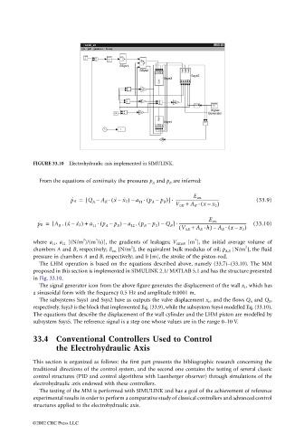
FIGURE 33.10 Electrohydraulic axis implemented in SIMULINK.
From the equations of continuity the pressures p A and p B are inferred:
p ˙ A = [ Q A – A K ( x – . p A – p B )] ------------------------------------------- (33.9)
E ers
.
. ˙ x ˙ 2) a 11 (–
V 0K + A K ( xx 2 )
.
–
(
p ˙ B = [ A R . x ˙ x ˙ 2) + a 11 ( p A – p B ) a 12 . p B – p 0 ) Q B ] ------------------------------------------------------------------- (33.10)
(
.
E ers
.
–
–
–
( V 0R + A R h) A R ( xx 2 )
.
.
–
–
2
3
3
where a 11 , a 12 [(N/m )/(m /s)], the gradients of leakages; V 0K,0R [m ], the initial average volume of
2
2
chambers A and B, respectively; E ers [N/m ], the equivalent bulk modulus of oil; p A,B [N/m ], the fluid
pressure in chambers A and B, respectively; and h [m], the stroke of the piston-rod.
The LHM operation is based on the equations described above, namely (33.7)–(33.10). The MM
proposed in this section is implemented in SIMULINK 2.1/ MATLAB 5.1 and has the structure presented
in Fig. 33.10.
The signal generator icon from the above figure generates the displacement of the wall x 1 , which has
a sinusoidal form with the frequency 0.5 Hz and amplitude 0.0001 m.
The subsystems Ssys1 and Ssys2 have as outputs the valve displacement x v , and the flows Q A and Q B ,
respectively. Ssys3 is the block that implemented Eq. (33.9), while the subsystem Ssys4 modelled Eq. (33.10).
The equations that describe the displacement of the wall cylinder and the LHM piston are modelled by
subsystem Ssys5. The reference signal is a step one whose values are in the range 0–10 V.
33.4 Conventional Controllers Used to Control
the Electrohydraulic Axis
This section is organized as follows: the first part presents the bibliographic research concerning the
traditional directions of the control system, and the second one contains the testing of several classic
control structures (PID and control algorithms with Luenberger observer) through simulations of the
electrohydraulic axis endowed with these controllers.
The testing of the MM is performed with SIMULINK and has a goal of the achievement of reference
experimental results in order to perform a comparative study of classical controllers and advanced control
structures applied to the electrohydraulic axis.
©2002 CRC Press LLC