
Page 87 - Theory and Design of Air Cushion Craft
P. 87
Flow rate coefficient method 71
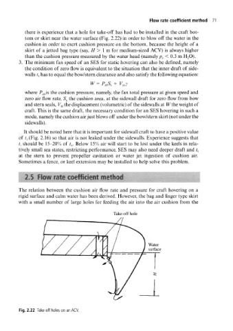
there is experience that a hole for take-off has had to be installed in the craft bot-
tom or skirt near the water surface (Fig. 2.22) in order to blow off the water in the
cushion in order to exert cushion pressure on the bottom, because the height of a
skirt of a jetted bag type (say, H > 1 m for medium-sized ACV) is always higher
than the cushion pressure measured by the water head (namely p c < 0.3 m H 2O).
3. The minimum fan speed of an SES for static hovering can also be defined, namely
the condition of zero flow is equivalent to the situation that the inner draft of side-
walls t, has to equal the bow/stern clearance and also satisfy the following equation:
W=P COS C+ y ioy
where P c0 is the cushion pressure, namely, the fan total pressure at given speed and
zero air flow rate, S c the cushion area, at the sidewall draft for zero flow from bow
and stern seals, F jo the displacement (volumetric) of the sidewalls at Wthe weight of
craft. This is the same draft, the necessary condition for an SES hovering in such a
mode, namely the cushion air just blows off under the bow/stern skirt (not under the
sidewalls).
It should be noted here that it is important for sidewall craft to have a positive value
of ?j (Fig. 2.16) so that air is not leaked under the sidewalls. Experience suggests that
should be 15-20% of t 0. Below 15% air will start to be lost under the keels in rela-
t {
tively small sea states, restricting performance. SES may also need deeper draft and { t
at the stern to prevent propeller cavitation or water jet ingestion of cushion air.
Sometimes a fence, or keel extension may be installed to help solve this problem.
15 PIJWfate coefficient method \ ' I "-. ;.r; {
The relation between the cushion air flow rate and pressure for craft hovering on a
rigid surface and calm water has been derived. However, the bag and finger type skirt
with a small number of large holes for feeding the air into the air cushion from the
Take-off hole
Fig. 2.22 Take-off holes on an ACV.