
Page 92 - Theory and Design of Air Cushion Craft
P. 92
76 Air cushion theory
2 2
so, using the relation sin = 1 — cos
f^p) = -B cHv sin a= -B cHv sin a r (2.39)
\ o< / max
where (dv/dO max is the maximum instantaneous wave pumping rate written as
= —nl c/A
a r
For instance, for the UK's SR.N5 hovercraft, in the case of )J2 = l c = 9 m, H = 0.8 m,
v = 35 m/s then (d F/d?) max = 150 m /s, i.e. the maximum power due to the wave pump-
ing is 172.7 kW. The total lift and propulsion power is 735 kW, of which about 30%
or 221 kW is used to power the lift fan. It can be seen, therefore, that the lift system
of SR.N5 can compensate the cushion flow rate consumed by the wave pumping
motion at this speed.
2.7 Calculation of cushion stability derivatives and
damping coefficients
In this section we will discuss the air cushion stability and hovering damping which
are very important parameters concerning the longitudinal and vertical motion of
ACVs hovering on a rigid surface. These parameters will greatly affect the natural
heaving frequency, seaworthiness and comfort of craft, but are only relative to the sta-
tic air cushion characteristics of ACVs. For this reason, these parameters are dis-
cussed in this chapter.
With respect to the SES, the air cushion stability and damping are also influenced by
the buoyancy and damping force of sidewalls, because they are immersed in the water.
The effect of sidewalls will be discussed at greater length in Chapter 9, though of course
it is not difficult to derive them by means of the methods demonstrated in this chapter.
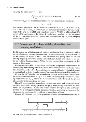
We take the ACV running over ground as an example and based on this the heav-
ing motion can be illustrated in Fig. 2.24. z c and are heaving displacement and veloc-
z e
ity respectively and z e, , denote the motion amplitude and velocity of the ground
z e
plane, similar to the amplitude for waves.
The ACV can be described as an elastic system with a spring and damper connected
parallel to each other. Strictly speaking, the spring and damping coefficients are non-
linear and asymmetric, i.e. they are rather different for upward and downward
motion. As a first approximation, assuming vibration movement with minute dis-
placement, the motion can be considered as approximately linear.
Thus an ACV running on a rough ground surface may be considered equivalent to
(=p
J L
' 7 / / / / 7 7 T / / / / / / / / /
Fig. 2.24 Heave motion of a hovercraft model on rigid surfaces.