
Page 83 - Theory and Design of Air Cushion Craft
P. 83
Static air cushion characteristics on a water surface 67
Fig. 2.17 Air leakage under SES sidewall with large air flow rate, hovering static over water.
cushion at the bow (also at the stern), can be illustrated as in Fig. 2.18. The flow rate
of an SES hovering statically on a water surface is normally calculated using the fol-
lowing assumptions:
• The air flow is non-viscous and incompressible.
• For simplicity, the outlet flow streamline chart can be considered as Fig. 2.18 and
takes the actual air clearance as </>(z b - t t) because of considering the contraction
of leaking air flow, where z b is expressed as the bow seal clearance, namely the ver-
tical distance between the craft baseline and the bow seal lower tip. <$> is the flow
contraction coefficient at the bow seal.
• The distribution of static pressure for leaking air flow is a linear function. As
shown in Fig. 2.18, the static pressure of leaking air flow is p n = p c for rj = 0, but
while rj = (z b - t {) <f>, p n = 0, where represents the ordinate with the original point
B and upward positive.
Thus the static pressure of leaking air flow at any point can be represented by
P, = P<V - W] (2.30)
According to the Bernoulli theory, the horizontal flow velocity at any point between
AB can be represented by following expression:
Q.5p aU: =p e- p c[\ - O) (2.31)
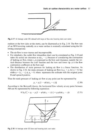
Fig. 2.18 Air leakage under SES bow seal hovering static over water.