
Page 82 - Theory and Design of Air Cushion Craft
P. 82
66 Air cushion theory
2.4 Static air cushion characteristics on a water surface
Static hovering performance of SES on water
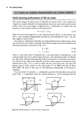
The various shapes of mid-sections of sidewalls are shown in Fig. 2.16; a typical one
is figure (a), namely sidewalls with perpendicular inner and outer walls near the water
surface. The craft total weight is supported by a combination of cushion lift and
buoyancy of the sidewall, which can be expressed as
J
|
W — p cb c + 2y Qy w (2.27)
TT/ „ O I 1 J7 i^ "> "7'\
2
where Wis the craft weight (N), p c the cushion pressure (N/m ), S c the cushion area
2 3
(m ), V G the volumetric displacement provided by each sidewall (m ) and y w the spe-
3
cific weight of water (N/m ).
According to Archimedes' principle, the relationship between cushion beam, inner
and outer drafts and width of sidewalls with different shape can be determined by the
following expressions and those in Fig. 2.16:
(2.28)
S c = B cl c
t (2.29)
t 0 ~ { = p c/y w
t is the outer draft of t the inner draft of / the
where 0 sidewalls (m), { sidewalls (m), c
cushion length (m), B c the cushion beam (m) and w the calculating width of sidewalls
(m). The inner sidewall draft gradually reduces as lift power is increased and cushion
air will leak from under both sidewalls once the cushion pressure exceeds the inner
sidewall draft (Fig. 2.17), as well as under the bow and stern seals, and form the
plenum type of craft, similar to the craft model '33' of HSEI and the US Navy
SES-100B. The drag of this type of craft decreases dramatically as lift power is
increased.
The outer draft of sidewalls, t 0, is dependent upon the lift fan(s) flow rate and the
inner draft, , is dependent upon the cushion pressure p c. The air leakage from the
/ ;
(a)
(c) (d)
Fig. 2.16 Sidewall thickness on various sidewall configurations.