
Page 291 - Thomson, William Tyrrell-Theory of Vibration with Applications-Taylor _ Francis (2010)
P. 291
278 Vibration of Continuous Systems Chap. 9
Data for the Tacoma Narrows Bridge
GEOMETRIC
/ = 2800 ft = span between towers
h = 232 ft = maximum sag of cables
= 39 ft = width between cables
d = 17 in. = diameter of cables
/z// = 0.0829 = 1/12 = sag-to-span ratio
b/l = 0.0139 = 1/72 = width-to-span ratio
WEIGHTS
w 4300 Ib/ft = floor weiight/ft along the bridge
w. 323 Ib/ft = girder weight/cable/ft
7T
Wc = J X ( I J J X 0.082 X 490 = 632 Ib/ft of cable
^ i(4300) + 320 + 632 = 3105 Ib/ft = total weight carried per cable
P = = 3105/32.2 = 96.4 lb • ft^ • s^ = total mass/ft/cable
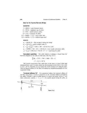
Calculated quantities. The cable tension at midspan is found from the
free-body diagram of the cable for half span. (See Fig. 9.4-2.)
= 232T - 3105 X 1400 X 700 = 0
:.T = 13.1 X 10^ lb
The vertical component of the cable force at the towers is equal to the total
downward force, and it is easily shown that the maximum tensile force of the cable
is 13.8 X 10^ lb. Therefore, we can neglect the small variation of T along the span.
Also the flexural stiffness of the floor in bending was considered negligible for this
suspension bridge.
Torsional stiffness Tb^. For suspension bridges, the torsional stiffness of
the floor and girders is small in comparison to the torsional stiffness provided by
the cables. Consider a pair of cables spaced b ft apart and under tension T. Let
three consecutive stations, / - 1, i, i + 1, be equally spaced along the cable, as
Figure 9.4-2.