
Page 71 - Thomson, William Tyrrell-Theory of Vibration with Applications-Taylor _ Francis (2010)
P. 71
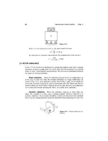
58                                Harmonically Excited Vibration   Chap. 3


                                                                     Figure 3.2-3.


                                  When  COis very much  greater than   the  same equation becomes
                                                          X =  ^   = 0.08 cm
                                                              M
                                  By solving the  two equations simultaneously,  the damping factor of the  system  is
                                                             0.08
                                                            2  X  0.60  =  0.0666
                       3.3  ROTOR UNBALANCE

                              In  Sec.  3.2  the  system was  idealized  to  a  spring-mass-damper unit with  a  rotating
                              unbalance acting in a single plane,  It is more likely that the unbalance in a rotating
                              wheel or rotor is distributed in several planes. We wish now to distinguish between
                              two types of rotating unbalance.

                                  Static unbalance.  When the unbalanced masses all lie in a single plane, as
                              in the case of a thin  rotor disk, the resultant unbalance  is a single radial force. As
                              shown  in  Fig.  3.3-1,  such  unbalance  can  be  detected  by  a  static  test  in  which  the
                              wheel-axle  assembly is placed on a pair of horizontal rails. The wheel will roll to a
                              position where  the  heavy point  is directly below the  axle.  Because  such unbalance
                              can be  detected without  spinning the wheel,  it  is called  static unbalance.

                                  Dynamic  unbalance.  When  the  unbalance  appears  in  more  than  one
                              plane,  the  resultant  is  a  force  and  a  rocking  moment,  which  is  referred  to  as
                              dynamic  unbalance.  As previously described,  a  static  test  may detect  the  resultant
                              force, but the rocking moment  cannot be detected without spinning the rotor.  For


                                                                     Figure 3.3-1.  System with static un-
                                                                     balance.