
Page 72 - Thomson, William Tyrrell-Theory of Vibration with Applications-Taylor _ Francis (2010)
P. 72
Sec. 3.3 Rotor Unbalance 59
Rotor
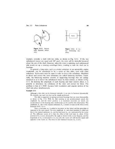
Figure 3.3-2. System Figure 3.3-3. A ro-
with dynamic unbal tor balancing ma-
ance. chine.
example, consider a shaft with two disks, as shown in Fig. 3.3-2. If the two
unbalanced masses are equal and 180° apart, the rotor will be statically balanced
about the axis of the shaft. However, when the rotor is spinning, each unbalanced
disk would set up a rotating centrifugal force, tending to rock the shaft on its
bearings.
In general, a long rotor, such as a motor armature or an automobile engine
crankshaft, can be considered to be a series of thin disks, each with some
unbalance. Such rotors must be spun in order to detect the unbalance. Machines
to detect and correct the rotor unbalance are called balancing machines. Essen
tially, the balancing machine consists of supporting bearings that are spring-
mounted so as to detect the unbalanced forces by their motion, as shown in Fig.
3.3-3. By knowing the amplitude of each bearing and their relative phase, it is
possible to determine the unbalance of the rotor and correct for them. The
problem is that of 2 DOF, because both translation and angular motion of the
shaft take place simultaneously.
Example 3.3-1
Although a thin disk can be balanced statically, it can also be balanced dynamically.
We describe one such test that can be simply performed.
The disk is supported on spring-restrained bearings that can move horizontally,
as shown in Fig. 3.3-4. With the disk running at any predetermined speed, the
amplitude and the wheel position a at maximum excursion are noted. An
accelerometer on the bearing and a stroboscope can be used for this observation. The
amplitude due to the original unbalance is drawn to scale on the wheel in the
direction from o io a.
Next, a trial mass is added at any point on the wheel and the procedure is
repeated at the same speed. The new amplitude and wheel position b, which are
due to the original unbalance and the trial mass mj, are represented by the vector
ob. The difference vector ab is then the effect of the trial mass alone. If the
/
position of mj is now advanced by the angle <>shown in the vector diagram, and the
magnitude of is increased to (oa/ab), the vector ab will become equal and
opposite to the vector oa. The wheel is now balanced because X^ is zero.