
Page 74 - Thomson, William Tyrrell-Theory of Vibration with Applications-Taylor _ Francis (2010)
P. 74
Sec. 3.4 Whirling of Rotating Shafts 61
ccw from the reference mark. Determine the correction weight to be placed on the
rim to balance the original disk.
Solution: The diagrams of Fig. 3.3-5 display the solution graphically. The vectors measured
by the instrument and the position of the trial weight arc shown in Fig. 3.3-5(b).
Vector ab in Fig. 3.3-5(c) is found graphically to be equal to 5.4 mm, and the angle (/>
is measured to be 107°. If vector ah is rotated 107° ccw, it will be opposite the vector
oa. To cancel oa it must be shortened by oa /a h = 3.2/5.4 = 0.593. Thus, the trial
weight = 2.5 oz must be rotated 107° ccw and reduced in size to 2.5 X 0.593 =
1.48 oz. Of course, the graphical solution for ab and (/> can be found mathematically
by the law of cosines.
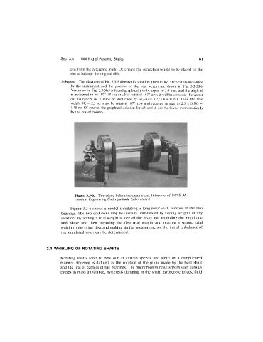
Figure 3.3-6. Two-plane balancing experiment. {Courtesy o f UCSB Me
chanical Engineering Undergraduate Laboratory.)
Figure 3.3-6 shows a model simulating a long rotor with sensors at the two
bearings. The two end disks may be initially unbalanced by adding weights at any
location. By adding a trial weight at one of the disks and recording the amplitude
and phase and then removing the first trial weight and placing a second trial
weight to the other disk and making similar measurements, the initial unbalance of
the simulated rotor can be determined.
3.4 WHIRLING OF ROTATING SHAFTS
Rotating shafts tend to bow out at certain speeds and whirl in a complicated
manner. Whirling is defined as the rotation of the plane made by the bent shaft
and the line of centers of the bearings. The phenomenon results from such various
causes as mass unbalance, hysteresis damping in the shaft, gyroscopic forces, fluid