
Page 359 - Thermal Hydraulics Aspects of Liquid Metal Cooled Nuclear Reactors
P. 359
Core thermal hydraulics 325
6.2.3.3.3 Deformations
Most simulations that can be found in literature only consider as-designed geometries.
However, from operating experience, it is known that deformations of the as-designed
nondeformed fuel assemblies will occur, not only as a result of off-normal operation
but also as a result of operational conditions and manufacturing accuracy. Such defor-
mations can be due to effects of tension of prestressed wires, contact pressure between
cladding and adjacent wires, thermal expansion, thermal and irradiation clad creep,
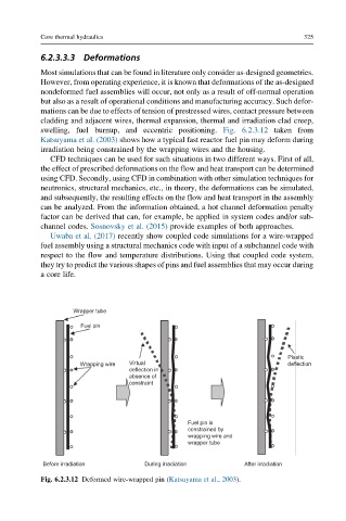
swelling, fuel burnup, and eccentric positioning. Fig. 6.2.3.12 taken from
Katsuyama et al. (2003) shows how a typical fast reactor fuel pin may deform during
irradiation being constrained by the wrapping wires and the housing.
CFD techniques can be used for such situations in two different ways. First of all,
the effect of prescribed deformations on the flow and heat transport can be determined
using CFD. Secondly, using CFD in combination with other simulation techniques for
neutronics, structural mechanics, etc., in theory, the deformations can be simulated,
and subsequently, the resulting effects on the flow and heat transport in the assembly
can be analyzed. From the information obtained, a hot channel deformation penalty
factor can be derived that can, for example, be applied in system codes and/or sub-
channel codes. Sosnovsky et al. (2015) provide examples of both approaches.
Uwaba et al. (2017) recently show coupled code simulations for a wire-wrapped
fuel assembly using a structural mechanics code with input of a subchannel code with
respect to the flow and temperature distributions. Using that coupled code system,
they try to predict the various shapes of pins and fuel assemblies that may occur during
a core life.
Wrapper tube
Fuel pin
Plastic
Wrapping wire Virtual deflection
deflection in
absence of
constraint
Fuel pin is
constrained by
wrapping wire and
wrapper tube
Before irradiation During irradiation After irradiation
Fig. 6.2.3.12 Deformed wire-wrapped pin (Katsuyama et al., 2003).