
Page 114 - Trenchless Technology Piping Installation and Inspection
P. 114
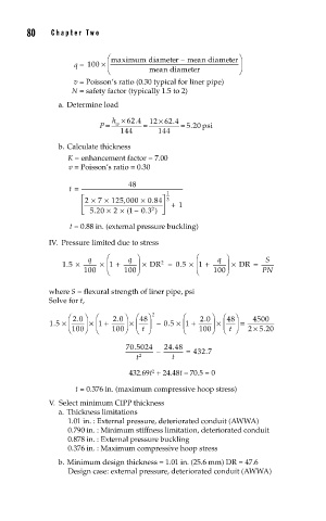
80     Cha pte r  T w o

                         ⎛ maximum diameter – mean diameter ⎞
                q =  100 × ⎜                              ⎟
                         ⎝         mean diameteer         ⎠
                v = Poisson’s ratio (0.30 typical for liner pipe)
                N = safety factor (typically 1.5 to 2)
            a. Determine load

                                .
                          h × 62 4  12  × 62 4 .
                        =
                                  =
                                           =
                       P    w                5.20  psi
                            144       144
            b. Calculate thickness
               K = enhancement factor = 7.00
               v = Poisson’s ratio = 0.30
               t =            48        1
                  ⎡ 2  × 7  × 125 000  × 0 84 ⎤ 3
                             ,
                                    .

                  ⎢                    ⎥ + 1
                                    2
                     .
                  ⎣ 520  × 2  × 1 ( – . )  ⎦
                                 03
               t = 0.88 in. (external pressure buckling)
          IV.  Pressure limited due to stress
                      15. ×  q  × ⎜ ⎛ 1 +  q  ⎞ ⎟ × DR 2  –  05 × ⎜ ⎛ 1 +  q  ⎞ ⎟ × DR  =  S
                                           .
                   100   ⎝   100 ⎠             ⎝    100 ⎠       P PN
          where S = flexural strength of liner pipe, psi
          Solve for t,

               ⎛ 20 ⎞  ⎛  20 . ⎞  ⎛ 48 ⎞  2  ⎛     ⎞  ⎛ 48 ⎞
                                                 .
               15. × ⎜  .  ⎟ × ⎜ 1 +  ⎟ × ⎜  ⎟   –.  ×  +  20 ⎟ × ⎜  ⎟ =  4500
                                       05 × ⎜ 1
                                                              ×
               ⎝ 100 ⎠  ⎝  100 ⎠  ⎝ t  ⎠    ⎝   100 ⎠  ⎝ t  ⎠  25 20
                                                                .
                                         .
                             70 5024   24 48
                                .
                                     –       =  432 7
                                                  .
                                t 2      t
                              432.69t  + 24.48t – 70.5 = 0
                                    2
                 t = 0.376 in. (maximum compressive hoop stress)
          V.  Select minimum CIPP thickness
            a. Thickness limitations
               1.01 in. : External pressure, deteriorated conduit (AWWA)
               0.790 in. : Minimum stiffness limitation, deteriorated conduit
               0.878 in. : External pressure buckling
               0.376 in. : Maximum compressive hoop stress
            b. Minimum design thickness = 1.01 in. (25.6 mm) DR = 47.6
               Design case: external pressure, deteriorated conduit (AWWA)