
Page 304 - Trenchless Technology Piping Installation and Inspection
P. 304
268 Cha pte r S i x
must be equal or exceed the drag force imposed on the pipe which
may be based a conventional Coulomb friction model. This theoreti-
cal model assumes that friction or drag forces on a moving body are
proportional to the local normal bearing forces applied to its surface,
with the proportionality constant designated as the “coefficient of
friction.” Such bearing forces may be due to the dead (empty) weight
of the pipe, pressure on the pipe due to vertical or lateral pressure
imposed by the soil, bearing/bending forces associated with pulling
a stiff pipe around a curve, or bearing forces resulting from (previ-
ously induced) axial tension tending to pull the pipe snugly against
any locally curved surfaces.
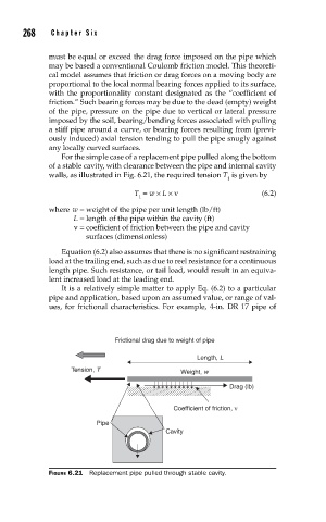
For the simple case of a replacement pipe pulled along the bottom
of a stable cavity, with clearance between the pipe and internal cavity
walls, as illustrated in Fig. 6.21, the required tension T is given by
1
T = w × L × ν (6.2)
1
where w = weight of the pipe per unit length (lb/ft)
L = length of the pipe within the cavity (ft)
ν = coefficient of friction between the pipe and cavity
surfaces (dimensionless)
Equation (6.2) also assumes that there is no significant restraining
load at the trailing end, such as due to reel resistance for a continuous
length pipe. Such resistance, or tail load, would result in an equiva-
lent increased load at the leading end.
It is a relatively simple matter to apply Eq. (6.2) to a particular
pipe and application, based upon an assumed value, or range of val-
ues, for frictional characteristics. For example, 4-in. DR 17 pipe of
Frictional drag due to weight of pipe
Length, L
Tension, T Weight, w
Drag (lb)
Coefficient of friction, ν
Pipe
Cavity
FIGURE 6.21 Replacement pipe pulled through stable cavity.