
Page 306 - Trenchless Technology Piping Installation and Inspection
P. 306
270 Cha pte r S i x
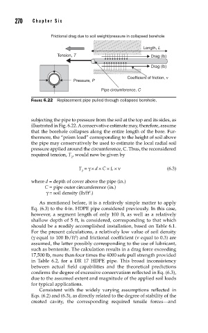
Frictional drag due to soil weight/pressure in collapsed borehole
Length, L
Tension, T Drag (lb)
Drag (lb)
Coefficient of friction, ν
Pressure, P
Pipe circumference, C
FIGURE 6.22 Replacement pipe pulled through collapsed borehole.
subjecting the pipe to pressure from the soil at the top and its sides, as
illustrated in Fig. 6.22. A conservative estimate may, therefore, assume
that the borehole collapses along the entire length of the bore. Fur-
thermore, the “prism load” corresponding to the height of soil above
the pipe may conservatively be used to estimate the local radial soil
pressure applied around the circumference, C. Thus, the reconsidered
required tension, T , would now be given by
2
T = γ × d × C × L × ν (6.3)
2
where d = depth of cover above the pipe (in.)
C = pipe outer circumference (in.)
γ = soil density (lb/ft .)
3
As mentioned before, it is a relatively simple matter to apply
Eq. (6.3) to the 4-in. HDPE pipe considered previously. In this case,
however, a segment length of only 100 ft, as well as a relatively
shallow depth of 5 ft, is considered, corresponding to that which
should be a readily accomplished installation, based on Table 6.1.
For the present calculations, a relatively low value of soil density
(γ equal to 100 lb/ft ) and frictional coefficient (ν equal to 0.3) are
3
assumed, the latter possibly corresponding to the use of lubricant,
such as bentonite. The calculation results in a drag force exceeding
17,500 lb, more than four times the 4000 safe pull strength provided
in Table 6.2, for a DR 17 HDPE pipe. This broad inconsistency
between actual field capabilities and the theoretical predictions
confirms the degree of excessive conservatism reflected in Eq. (6.3),
due to the assumed extent and magnitude of the applied soil loads
for typical applications.
Consistent with the widely varying assumptions reflected in
Eqs. (6.2) and (6.3), as directly related to the degree of stability of the
created cavity, the corresponding required tensile forces—and