
Page 309 - Trenchless Technology Piping Installation and Inspection
P. 309
Pr oject Considerations for Pipe Replacement Methods 273
pressure on the pipe. In general, the detailed consideration of the
interaction of the various phenomena, and the consequences for the
product pipe is relatively complex. In particular, it is not clear that the
model represented by Eq. (6.6) is appropriate for the asymmetric soil
pressures applied to a partially constrained pipe in the cavity created
by the bursting operation. However, for the present purpose of devel-
oping an easy-to-apply planning guide, it is again desired to make
some simplifying assumptions. Thus, the effect of the estimated
asymmetric earth pressure, assuming a locally collapsed cavity, is
compared to the critical load as indicated in Eq. (6.6), recognizing that
the procedure may be somewhat conservative due to a degree of lat-
eral constraint that may be provided to the pipe.
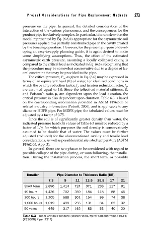
The critical pressure, P , as given in Eq. (6.6) may be expressed in
cr
terms of an equivalent head (ft) of water, for idealized conditions in
which the ovality reduction factor, f , and tension reduction factor, f ,
o R
are assumed equal to 1.0. Since the (effective) material stiffness, E,
and Poisson’s ratio, μ, are dependent upon the load duration, the
critical pressure is also dependent upon duration. Table 6.3 is based
on the corresponding information provided in ASTM F1962-05 or
related industry information (Petroff, 2006), and is applicable to any
diameter HDPE pipe. For MDPE pipe, the tabulated values must be
adjusted by a factor of 0.75.
Since the soil is of significantly greater density than water, the
indicated pressure head (ft) values of Table 6.3 must be reduced by a
factor of 1/γ, for which purposes the soil density is conservatively
assumed to be double that of water. The values must be further
adjusted (reduced) for the aforementioned ovality and tensile load
considerations, as well as possible initial elevated temperature (ASTM
F1962-05, App. 3).
In general, there are two phases to be considered with regard to
possible collapse of the pipe during, or soon following, the installa-
tion. During the installation process, the short term, or possibly
Duration Pipe Diameter to Thickness Ratio (DR)
7.3 9 11 13.5 15.5 17 21
Short term 2,896 1,414 724 371 238 117 91
10 hours 1,436 702 359 184 118 88 45
100 hours 1,205 588 301 154 99 74 38
1,000 hours 1,019 498 255 131 84 62 32
50 years 649 317 162 83 53 40 20
TABLE 6.3 Ideal Critical Pressure (Water Head, ft) for Unconstrained HDPE
(PE3608) Pipe (73°F)