
Page 160 - Tunable Lasers Handbook
P. 160
140 Charles Freed
in 1984 [11 I] and 1985 [76], respectively. Here I can only give a few glimpses
into some of the findings.
In [76.111,112] we find anomalous blue shifts of CO, absorptions with pres-
sure that were in the range of 40 to 90 kHz/Torr for the 626, 636, 828, and 838
CO, isotopic species (see Table 1 of [78] or [ 11 11). Figure 19 shows a sample of
the plots of typical pressure shift data sequences, all “blue” shifts, one for each of
the four CO, isotopic species that were measured. Because the CO, pressures
used in the frequency stabilization cells were typically in the 50 k- 15 mTorr
range, the implication is that there is a systematic 3.6 k 2.2 kHz frequency shift
that we chose to ignore when generating the predicted [37] absolute frequencies.
Our decision not to take into account pressure shift was based on the considera-
tions that follow.
The anomalous blue pressure shifts we measured could not be explained by
any of the theories that we explored [ 11 21 or that were suggested to us because
all of them predict red pressure shifts. The pressure shifts we measured were
very small and necessitated the improvement of our experimental apparatus and
measurement technique well beyond what was available when most of our data
were gathered for the database given in Bradley et ill. [37].
Consistent and reproducible pressure shifts were only obtained after we ini-
tiated a new measurement technique in order to eliminate frequency-offset errors
caused by the nonzero slope of the power-versus-frequency characteristics of the
lasers over the frequency range of the nonlinear saturation resonance dip. This
nonzero power slope is a universal problem in most stabilization schemes used
with lasers. Furthermore, this so-called “instrumental” frequency shift has a qua-
dratic dependence on pressure and may easily dominate over the true pressure
shift at stabilization cell pressures greater than about 60 mTorr. Moreover, the
sense of this “instrumental” frequency shift can be either red or blue, depending
on the adjustment of the grating position in the CO, - laser as illustrated by the
data shown in Fig. 20.
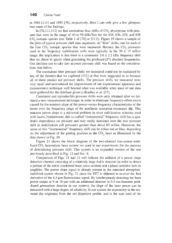
Figure 21 shows the block diagram of the two-channel line-center-stabi-
lized CO, heterodyne laser system we used in our experiments for the purpose
of determining pressure shift. This system is an expanded version of the one
previously described in Fig. 13 and Sec. 8.
Comparison of Figs. 21 and 13 will indicate the addition of a power slope
detection channel consisting of a relatively large AuGe detector (in order to detect
a portion of the entire combined beam cross section) and a phase-sensitive lock-in
amplifier. The power slope signal is already present in the saturated absorption-
stabilized system shown in Fig. 21 since the PZT is dithered to recover the first
derivative of the 4.3-pm fluorescence signal. By synchronously detecting the laser
power output at 9 or 10 pm with an additional detector [a 0.3-cm-diameter gold-
doped germanium detector in our system), the slope of the laser power can be
measured with a large degree of reliability. In our system the asymmetry in the res-
onant dip originates from the net dispersive profile, and is the sum total of the